The Motivation
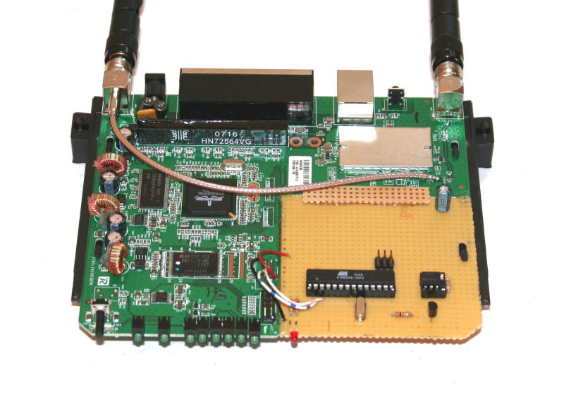
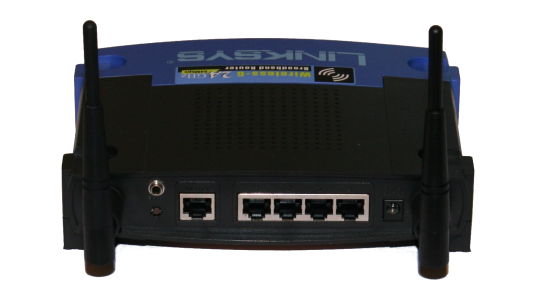
The Linksys WRT54GL wireless router is a very nice device for us hobbyists. Not only is the firmware open-source, so that the community has come up with several different new and fancy firmwares. The hardware designers at Linksys were kind enough to leave more than 25% of the board space unused. They even have cut it out, leaving the remaining area for our own ideas. As you can see in the pictures, I was able to add rather big additional board, without any modification to the housing.  The only change that you see for the outside, is the 3.5mm jack on the back side (upper left).
The Linksys engineers have also made two serial ports available internally, which are free for the user to use, at least if you are using the DD-WRT firmware that I am working with.
As you can log into this router via SSH (secure shell, a telnet like remote console but completely encrypted) from your local network, as well es via the Internet, I found it too tempting to use the router for remote controlling parts of my IT landscape at home. The first idea that I could come up with, was to use this for switching on my main server via the router. This way, the server does not waste electrical power while it is not needed. Also there is no danger for the server of being hacked, as it is not even running most of the time. Whenever I want access to the server from abroad, I simply log into the router, issue a special command and the server starts booting.
The Solution
The simplest and most flexible way of converting a serial (RS232-like) signal to parallel inputs/outputs is via an Atmel AVR microprocessor with some software in it. The AVR family of devices incorporate a 8bit RISC architecture, the flash memory, the RAM and everything else needed to run an embedded system. So they are true single-component devices. They can even run on internal clock sources if the exact clock frequency is not critical. In my case I have spend a 3.686MHz crystal, to ensure stable communication on the RS232 interface.
The few components needed, I have simply put on an experimental board which I had cut to exactly the remaining area inside the WRT54GL routers housing. The mechanical connection between the two boards is established with strong two-component glue. There is even a 4th plastic hook in the bottom housing part, so a milled long-hole in my board added additional mechanical stability. The connection to the PC is done via a 3.5mm jack that I added to the back side of the plastics housing.
The router runs internally on 3.3 volts, so I have simply used this voltage to run the AVR as well. This way we don’t have to do any level shifting between the serial interface of the router and the AVR. We can simply connect the TXD (transmit data) line of the router to RXD (receive data) of the AVR and vice versa.
Via a general purpose transistor, the AVR controls an optical coupler which can pull the power switch line of the server to ground, to trigger it’s booting.
The Software
The software of the AVR is quite straight forward. As several C compilers are available for AVR, there is no point in doing the software in assembly language. I have used the GNU C compiler which is available both for Linux and Windows development environments.
You can download the software both in source and as pre-compiled binaries here for usage in your non-commercial projects.
- The WRT54GL-add-on Software, Version 1.0 (Source code in C)
- The appropriate makefile for compiling the source code with the GNU C compiler.
- The WRT54GL-add-on Software, Version 1.0 (.hex file for direct download to a AVR Mega8)
The circuit diagram
(Click on the picture for a higher resolution view)
The Usage
So, how do we use the whole thing? Well, that not so tricky.
A) Configure your router (which is usually operated as access point) in client mode, so it connects to your router at home as another client, just like as it would be another PC or Laptop. An extensive description how to do this is available here in English. A somewhat more graphical description in German is available here, the latter is what I used successfully. Additionally you have to switch on the SSH damon in the routers web interface (Services – Services – SSHd enable on Port 22). If you want to log in via the internet later, also enable the remote SSH access (Administration – Management – Remote Access SSH enable).
B) Go to your home routers web interface and check which IP address your WRT54GL did get. Lets assume that is 192.168.178.28. Now you need a SSH client on one of your PC’s. If you are using a Linux system, simply open a command line shell and type “ssh root@192.168.178.28”. If you should be running Windows, you can download the Putty client and connect with it to 192.168.178.28 on port 22. When being asked as whom you would like to log in say “root”. The password that is set by default is “admin”, you may want to change it via the graphical interface of the WRT54GL router if you make the router available to the outside world via a port forward on your access point router.
C) Your are logged into your WRT54GL router now, which is running the DD-WRT software. What you get should look somewhat like this:
herbert@AMD64:~$ ssh root@192.168.178.28
DD-WRT v24 vpn (c) 2007 NewMedia-NET GmbH
Release: 09/13/07 (SVN revision: 7957)
root@192.168.178.28’s password:
==========================================================
____ ___ __ ______ _____ ____ _ _
| _ \| _ \ \ \ / / _ \_ _| __ _|___ \| || |
|| | || ||____\ \ /\ / /| |_) || | \ \ / / __) | || |_
||_| ||_||_____\ V V / | _ < | | \ V / / __/|__ _|
|___/|___/ \_/\_/ |_| \_\|_| \_/ |_____| |_|
DD-WRT v24
http://www.dd-wrt.com
==========================================================
BusyBox v1.4.2 (2007-09-13 21:49:27 CEST) Built-in shell (ash)
Enter ‘help’ for a list of built-in commands.
~ #
D) Now you can send commands to the AVR by simply forwarding them to the serial interface device. Type “echo help > /dev/tts/1” to trigger the help output from the AVR. Don’t be disappointed if there is no reaction to your command. Your shell is showing the stdout channel of your router. If you would like to see the response from the AVR, open a second ssh connection to the router (just like described above) and redirect the feedback from the serial interface device to your shell by typing “cat < /dev/tts/1”. Now if you go back to your first shell and try the help command again, you will see the output of the AVR on the second shell:
herbert@AMD64:~$ ssh root@192.168.178.28
DD-WRT v24 vpn (c) 2007 NewMedia-NET GmbH
Release: 09/13/07 (SVN revision: 7957)
root@192.168.178.28’s password:
==========================================================
____ ___ __ ______ _____ ____ _ _
| _ \| _ \ \ \ / / _ \_ _| __ _|___ \| || |
|| | || ||____\ \ /\ / /| |_) || | \ \ / / __) | || |_
||_| ||_||_____\ V V / | _ < | | \ V / / __/|__ _|
|___/|___/ \_/\_/ |_| \_\|_| \_/ |_____| |_|
DD-WRT v24
http://www.dd-wrt.com
==========================================================
BusyBox v1.4.2 (2007-09-13 21:49:27 CEST) Built-in shell (ash)
Enter ‘help’ for a list of built-in commands.
~ # cat < /dev/tts/1
AVR Mega8 as WRT54GL add-on is alive…
(c) 2008 by Herbert Dingfelder, DL5NEG
Available commands:
ATPCB Starts the connected PC
ATPCOFF Forces the PC hard off
HELP Shows this help text
E) To trigger the optical coupler that can switch on your PC, simply use the respective command (AT PC Boot): “echo atpcb > /dev/tts/1” and the power switch line of your PC will be drawn to ground for one second, the LED (which can shine though the front of the housing) will be on for that time. If your server happens to hang completely, you can remotely switch it off by using the “echo atpcoff > /dev/tts/1” command, which holds down the power switch line for 10 seconds.
6. What more is possible with the AVR in the WRT54GL?
Well, here only your imagination sets the limit. In this configuration the Mega8 AVR has still 13 unused GPIOs (general purpose input/output) of which 6 are even 10bit ADCs (analog to digital converters). The program memory of the Mega8 is only 10% full with the given software. On the experimental boards there is still plenty of room left for more components.