Motivation
I had developed the 7 MHz CW TRX for my first trip to the US. The receiver worked very well. (Actually a lot better than here in Europe, since they do not have high power broadcast stations on 7.1 MHz.) The transmitter is also quite ok. 1.5 Watts is not a lot, but that was the compromise I had chosen to save current. The thing that was not really good was the temperature stability in transmit mode. While it was no problem at all to listen to a certain station for a couple of minutes without retuning, the LO really started to drift in TX mode. If I made a longer transmit, giving my name, my QTH and the report, I really had a hard time to recognize the other station when I was back in RX mode. And it was really hard to find friends on a certain frequency, since the analog frequency readout was quite coarse.
Solution
I decided I needed a PLL (phase-locked-loop) synthesizer with a crystal as frequency standard. I did not know about a PLL IC for 7 MHz that would give a small enough step width. Having a RX filter that is only a few hundred Hertz wide, I needed a maximum of 100Hz as tuning step width. So I chose a quite unusual solution. I used a 900 MHz VCO (readily available from a couple of suppliers, usually used in mobile telephones) and a MB15E07 PLL synthesizer from Fujitsu. It can give a step width of 8kHz at 1GHz. The 900 MHz signal is divided by 128 by a cheap U893 prescaler from Temic Semiconductors. This reduces the frequency to 7MHz and the step width to 62.5 Hz. For programming the PLL, I need a micro controller anyway, so I decided to remove the analog instrument and replace it by a LCD-Display. This way I could realize a digital frequency readout. To be frank, I liked the analog instrument, but the digital frequency readout makes it a lot easier to find your QSO partner if you have an appointment (a sked) with a friend.
Realization
I have made a SMD circuit board, carrying the RF stuff on one side and the digital stuff on the other side.
Digital side
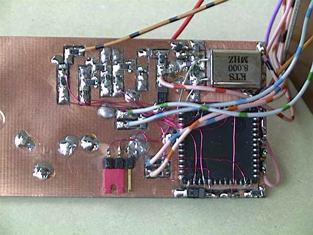
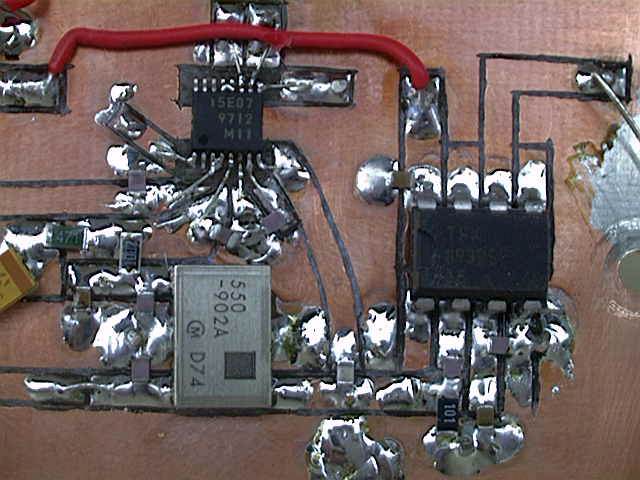
RF side
Then I have removed everything that belonged to the old VCO, including the frequency shifter for TX operation. This not necessary anymore, since the CPU can simply add 12 steps of 62.5 Hz, to change the frequency by 750Hz. This is the value I had with the old solution (well roundabout, the shift was not so well defined with the free running oscillator).
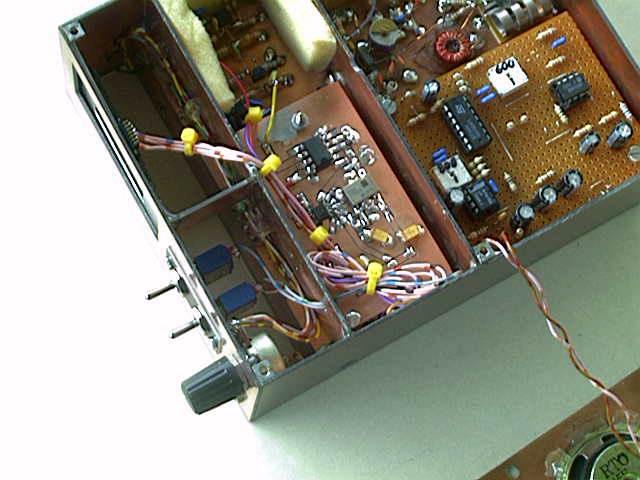
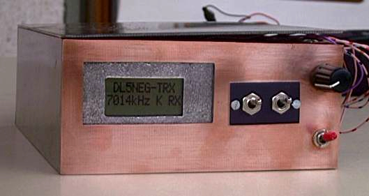
I fixed the new board with a screw and metal bolt at the space where the old VCO was located before. See for yourself how it looks now.
As I mentioned before, I have also removed the analog instrument and have replaced it by a small LCD display
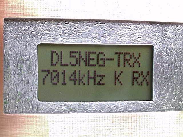
And the big tuning wheel had to be removed to make space for two keys that are used now to tune up and down (see picture of the new front).
There is a software function that waits a short while, after the first frequency step. This makes it possible to tune in single steps (62.5Hz wise). If you press one key a little longer the CPU starts to tune continuously at a speed that makes it possible to find frequencies with potential QSO partners.
Schematics
There are not a lot of really new ideas in the schematics. In the RF-part you can see the 902 MHz VCO, the PLL synthesizer and the divider. The PLL is programmed via a 3-wire-bus interface from the CPU. The divider can be used for 3 different division ratios (64,128,256). It is fixed set to 128 (pin 5 to Vcc). The loop filter elements are chosen in a way to give the loop a corner frequency of roundabout 120Hz. I have checked the sidebands (8kHz away from the carrier) and they are at least 70dB below the carrier.
The digital part consists mainly of the 68HC11 CPU. The 3-wire-bus to the PLL includes voltage dividers, to reduce the voltage form 5Volts to 3.8Volts. Only one thing is really tricky and saves a lot of additional components: The LCD needs a negative voltage of -1.8 Volts. In order to create that voltage, I have led the 8MHz reference signal over two capacitors that have a BAT64 Schottky barrier diode between them. The signal is not harmed by that, only the DC part of the digital signal is pushed down below 0 Volts. With a large resistor (10kOhm) and two capacitors, I filter out the AC part of the signal and … hurray, here we have -1.8 Volts!
Firmware
The 68HC11 version that I have used has only 512Byte of EEPROM for the program code. You may be able to imagine that this is not a lot, if the software has to include the driver routines for the LCD display and the PLL circuit. It also has to check the user keys, calculate the bits for the PLL and show the frequency in kHz in the display. In TX mode it has to add 750Hz to the frequency to achieve the necessary frequency shift. When the 512Bytes were used up, I was not really done with everything, so I had to optimize the code. And I really took no prisoners while squeezing out the bytes. Therefore the code is really hard to read now (and the commends are only in German, by the way.) One thing I had to give up was displaying the exact fraction of a kHz in the LCD display. It simply consumed too much memory. Now it shows only the kHz part of the frequency and the rest is show as A=0, B=62.5Hz, C=125Hz, D=187.5Hz and so on. If you should be interested to have a look at the assembler code anyway, I will be glad to e-mail it to you on your Email request.