What is it good for?
Well, I guess every hobbyist some-when comes up with ideas of controlling or measuring something with a PC. Of course the idea is tempting, there are so many easy-to-learn program languages available for PCs today that almost everyone can write the software to switch on the light when he is on vacation, to control these cute little toy robots or to measure the amount of rain over the day. So if you are a somewhat advanced hobbyist, the application is only limited by your fantasy (i.e. the sky is the limit).
But: How can we close the gap between a few lines of software code and a real electrical signal outside of the computer? Of course there are many solutions to this problem, many of them require serious “hacking” to access one of the i/o ports of a computer. (Especially Windows NT4 required very advanced programming skills if you wanted to use i/o ports for non-standard applications). One port that is easy to access from a software point of view is the serial RS232 port (COM1, COM2, etc.). All modern software development tools support the RS232 port, so its usually no problem at all to send or receive data via this port.
What makes the RS232 very unattractive for hobbyists is the fact the data bits are in a serial time synchronous format with critical timing and a relatively complex start/stop-bit overhead. To make it even worse the bit levels are -12V for high and +12V for a low bit, so connecting RS232 signals to a circuit that uses 5V logical levels is not trivial either. Simply forget about connecting the RS232 directly to a relay driver stage or things like that.
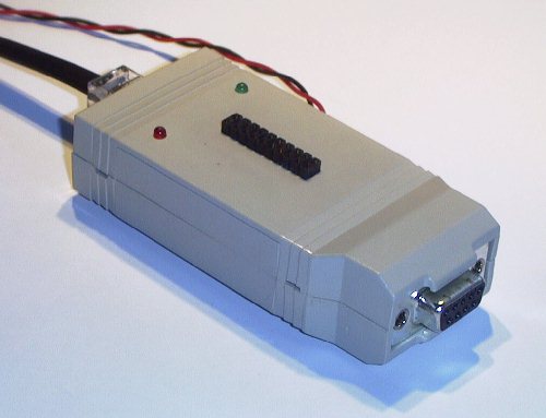
And that is where this circuit comes in. It converts a RS232 bit stream into standard digital signal inputs and outputs. It even provides you with a couple of 10bit ADCs so you can read analog voltage levels into your PC with a resolution of 1024 different levels.
How does it work?
First of all the RS232 levels are converted to normal logical levels by a MAX3232. This is a standard IC that includes voltages converters which are able to produce 2xVcc and -2xVcc. Even if you use only 3.2V as Vcc, it will give you somewhat over plus and minus 6 volts, that is more than sufficient for a reliable operation of the RS232 port. I have used Vcc=3.2 Volts but I assume for most of you it is more convenient to use Vcc=5V since that will give you standard TTL level signals at the in/out ports. Since the ADC has a resolution of 10bits, the max. value it can deliver is 3FF hex. That value always corresponds to a input level that is equal to Vcc. Feel free to choose any Vcc voltage between 3Volts and 5.5Volts, both ICs will work fine in that range according to their specification.
The second step is the conversion from parallel digitial data bit into the RS232 serial bit stream and vice versa. For that we use a AT90LS4433 8bit microprocessor. It has a hardware-implemented RS232 port, a number of general purpose digital i/o-ports and internal 10bit ADCs. All it takes to make the whole thing flying is a software for the micro that reads commands from the RS232 port and reads/sends bits and/or reads analog voltage levels.
The Software
Here is the assembler code that can be assembled in ATMELs AVR-Studio.
- inoutbox.asm (Assembler source code for those who are interessted.)
If you don’t care about the source code and just want to make it work you can use this files.
- inoutbox.hex (Hex-File which can be loaded into the CPU directly.)
- inoutbox.eep (EEPROM-File which can be loaded into the CPU directly.)
Both, the .hex and the .eep files must be loaded into the micro, otherwise it won’t work! For software download I recommend to use one of the many SPI in-circuit programmers. The “Atmel-standard” in-circuit programming connector can be seen in the schematic (marked SPI connector).
How can I communicate with the interface?
Set your RS232 (COM1, COM2, whatever you use) to 9k6, 8, N, 1 (Baud rate 9600 b/s, 8 data bits, no parity bit, 1 stop bit). The interface accepts the following commands via the RS232 port:
Command Meaning What is it good for?
sb <bit> set bit sets one of the digital outputs of the interface to high
cb <bit> clear bit sets one of the digital outputs of the interface to low
rb <bit> read bit reads one of the digital inputs and sends the result back to the PC
ra <bit> read ADC reads one of the ADC inputs and sends the result back to the PC
ei <string> echo input echos the string that was received by the micro (for debugging)
If you use a terminal program to communicate with the interface you can use the BACKSPACE key to correct your input.
Here are a few examples to illustrate what you strings you have to send to the interface to perform certain actions.
sb 3
cb 0
ra 2
ei This is a test…