What is it good for?
A lot of radio amateurs are afraid of building stuff for GHz-frequencies, because they fear that they have no chance to measure at these frequencies. Well, the most interesting parameters of a signal are frequency and amplitude. Reasonably priced frequency counters up to 3GHz are widely available now, but RF power meters are still quite expensive. This circuit transforms a RF signal into a DC voltage level, which can easily be measured with a low-cost multimeter. Using the graph further down this page, you can then determine the RF signal level.
How does it work?
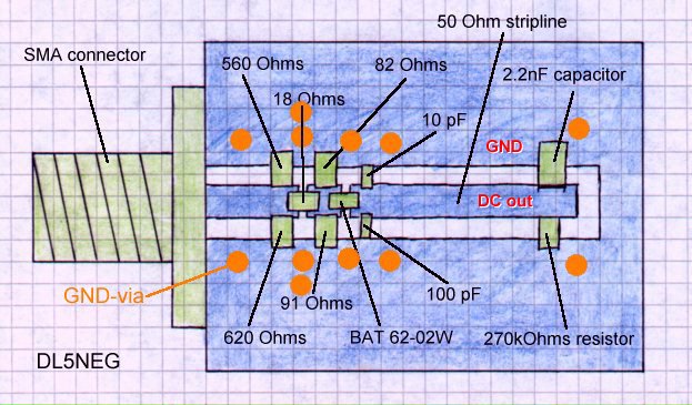
The 5 resistors at the input form a combined 3dB resistive pad and RF termination. The RF diode (BAT62-02W) rectifies the signal, the capacitors on the DC side form a broadband short circuit for RF. It is very important for a flat frequency response, to have the different capacitance values as shown in the arrangement below (the pF very close to the diode) .
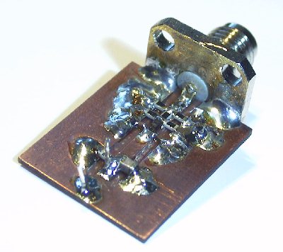
The mounting drawing below is for scaling. One unit is one millimeter. The ground vias are very important for a constant frequency response. The more the better. I have marked my vias in the drawing to give you an idea where the vias are most important. I have used silver coated copper wire with 1mm diameter, the thicker the better. I have used FR4 PCB material with a thickness of only 0.8mm to keep the ground vias short. You can use 1.5mm material as well but the stripline has to be 2.5mm wide then.
RF input is the SMA connector on the left side of the circuit board. The rectified DC voltage is present on the stripline right to the diode. Just measure the voltage across the red markings GND and DC out. See below for figuring out how much RF input power causes which amount of DC voltage at the output.
How can I convert the DC level to the RF power level?
I have built a number of these circuits and the variation from one sample to another is very small. So if you built such a circuit for yourself and stick to the mounting drawing above, you can use my measured values. You can even use BAT62 diodes in different packages for frequencies up to 2.5GHz. Above 2.5GHz it makes sense to use the very small package that I have used, to keep the self-resonance frequency high.
Below you can see the DC output voltage that the circuit gives at certain input power levels at certain frequencies.
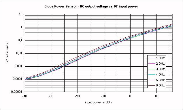
As you can see, the DC output voltage is practically independent of the frequency up to 3GHz. Above 3GHz there is a slight frequency dependency, but using the graph above you can still determine the RF power with high accuracy.
If you feel that the graph does not give you precise enough information you can download the complete table as text file.
Any questions? Just don’t hesitate to contact me by email and I will be glad to provide you with answers. You will find my email address on my main page.