![]()
Introduction
Many remotely controlled multicopters, better known as drones, have GPS receivers on board for various purposes. The very small toy drones however, like the popular X5C, have a weight of roughly 100 grams only, and are not capable of lifting the weight of typical GPS trackers. In order to still be able to record the flight path, including height and speed, I have developed and successfully tested the circuit and firmware that is published on this page. The total weight of the complete electronics, including the connection wires, is about 10 grams. The main advantage of this circuits (besides the fun of developing it myself) is the fact that is runs directly on the flight battery of the drone. This avoids the need for adding another battery, which would put an unacceptable weight on the drone.
Practical tests have shown that a X5C is able to carry the 10g of additional weight, but it is already recognizable, that the vortex ring effect kicks in more easily compared to flying without the extra weight. One possible counter action is to remove the camera together with the battery lid, which reduces the weight by 8g, bringing the overall weight basically back to the original one.
Hardware
The hardware consists of basically two parts. The first one is an Adafruit ultimate GPS engine v3, which can be ordered for around 50€ from Amazon or Ebay.
The second part is my own circuit, which has an ATtiny84A microprocessor as core component. A 32kByte serial EEPROM is connected to the ATtiny, to store the GPS data that is generated by the GPS engine.
As most of the magic happens in the firmware of the ATtiny (firmware can be downloaded below), the electronics is rather simple and quite quick to copy. I do admit that I have used a stereo microscope (10x magnification) for some of the soldering, but it is well possible without. I have use the SMD version of both chips, but at the expense of 2-3 grams of extra weight, you can use the larger DIL packages as well.
What is not shown in the schematic below, is a 1000µF capacitor that was needed on a Syma X5C drone, to avoid voltage drops well below 3.3V, even with a fully charged battery. Apparently the motor controllers are based on pulse width modulation, as the battery voltage drops down at 14.7kHz by almost one volt. That voltage drops resets both the GPS and the ATtiny. With the large electrolytic capacitor everything works fine, the voltage drop is reduced to a few hundred millivolts. As the capacitor really kills the aesthetics of the circuit, I will probably place it inside the drone to stabilize the battery voltage there. That is were it belongs and I think the designers of the X5C should have added it there.
Click on the schematic below to download a high quality PDF file.
![]()
Firmware
The firmware realizes essentially a node between three ports.
- The connection to the GPS unit, via a RS232 software UART
(for reading the output data from the GPS in NMEA message format) - The connection to the serial EEPROM via a software I2C interface
(for storing the data into the EEPROM and to read it back later) - The connection to a PC interface, via a second RS232 software UART
(for downloading the collected data after the flight)
The ATtiny84A does not have hardware UARTs, so I had to implement the UARTs completely in software. The design utilizes the 16bit hardware counter, including both hardware compare units. One compare unit triggers after one bit length, which is 104µs at 9k6 baud, the other one triggers at 52µs, to read incoming data exactly in the middle of each bit.
Doing the UARTs in software has one big advantage over a hardware UART, that is available in many of the more costly ATmega microprocessors: You can pick any output and input pin you want for UART communication. That allows to pick two of the pins, which are used for the 6pin ISP (in-circuit-programmer) interface. Since every gram of weight is crucial for this application, it is very nice to need only one mechanical connector, that can be used both for flashing new firmware and for downloading the stored data from the EEPROM to a PC.
In addition to recording the GPS data, the firmware also reads out one of the internal 10 bit ADCs in the ATtiny84A. The battery voltage is fed to the ADC input via a voltage divider, that reduces the voltage to a level below the 3.3V supply, which is also used as a voltage reference. From the ADC reading, the battery voltage in millivolt is calculated and stored in the EEPROM together with the GPS data.
Source code of the firmware (published under GNU GPL v3)
Fuse bit setting for the ATtiny84A
In order to have the ATtiny84A configured for this application, some of the low byte fuse bits must be adapted from the default setting to specific settings, which are in detail:
CKDIV8 bit7 1 do not divide clock by 8
CKOUT bit6 1 no clock output to a pin
SUT1 bit5 1 select startup time for crystal with slow rising power => 11
SUT0 bit4 1
CKSEL3 bit3 1 External crystal
CKSEL2 bit2 1 Clock >8MHz => 111
CKSEL1 bit1 1
CKSEL0 bit0 1
That means the fuse low byte must be set to 0xFF. Using the avrdude software, the command line for doing this is (assuming a AVR ISP MK2 programmer):
sudo avrdude -c avrispmkII -P usb -p t84 -U lfuse:w:0xff:m
PC Software to downloading the data
Downloading the raw data to a PC is really simple. All it takes is a RS232 level converter, to convert the +3.3V TTL signals on the 6pin connector to valid RS232 levels. If your PC does not have a RS232 any more, you may want to use a RS232 to USB converter in addition.
In principle a simple terminal software can be used. More comfortable is to use the PC software, that I have written for this purpose. It does not only receive the raw data, but packs it neatly into a valid .gpx file, that can be opened with one of the many GPS data viewers like Viking, GPSprune, GPSviewer, etc. The software is written in C and is intended to run on a Linux desktop PC or on a cheap RaspberryPi board.
In a terminal, just set the baud rate to 9k6 8N1, connect the board and send ‘X’ characters until the circuit answers with ‘ok’. Since the UART has no hardware buffer, it cannot receive while GPS data is written to the EEPROM. That creates some blackout time on the interface, which results in a roughly 50:50 chance, every time an ‘X’ is sent. As soon as the ‘ok’ comes back, writing to the EEPROM is stopped, the UART is fully responsive and all inputs will be processed reliably. Send a ‘d’ to trigger a dump of all 32kBytes of EEPROM data. Then enter command mode again with ‘X’ and after the ok send an ‘e’ to erase the memory to make space for new recordings.
The command mode has a timeout of 10 seconds after the ‘ok’. If no further input is received, the circuit resumes normal recording operation.
Source code for the PC software in C (published under GNU GPL V3)
Practical results
One very interesting result, that would be almost impossible to get without such a tracking device, is to see the battery voltage and the elevation of the drone over time.
In the diagram below, which I have put together in LibreOffice based on the extracted data, it can be seen that I have plugged in a fresh battery three times during recording. These are the flat lines at 4200mV in the red battery line. It can also be seen that the battery voltage drops quite heavily under load. I have landed the drone a few times, which is visible in the upward peaks when the voltage level recovers up to 3900mV.
The blue line shows the elevation. The actual elevation of the green field is apparently around 340 meters above sea level, while the highest elevation the drone had climbed to was around 370 meters.
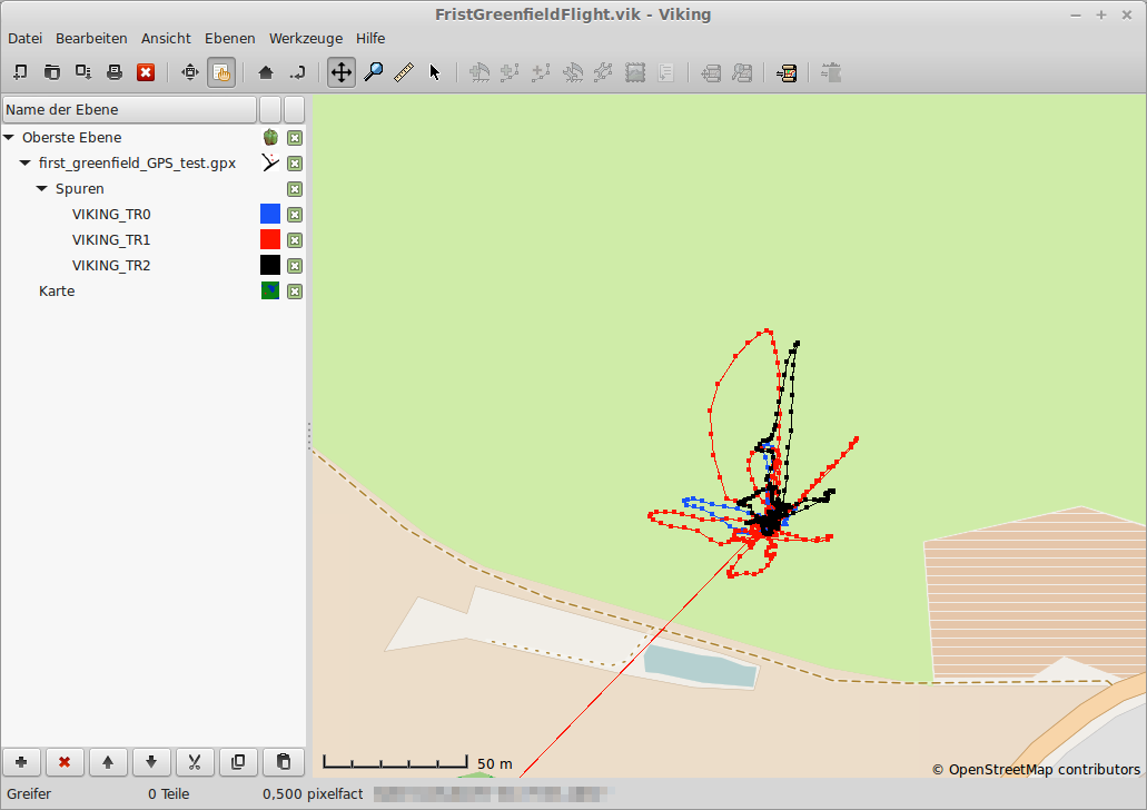
Since the PC software generates valid .gpx files, the data can be loaded directly into map software like Viking. Also here it can be seen that I used fresh batteries three times. The software has stored three separate tracks, one for each power-up of the tracker.
More pictures
![]()
![]()
User Manual
Simply connect the circuit to the battery of your drone. If the supply voltage should be significantly noisy from the motor controllers, use a large electrolytic capacitor like shown in the picture above.
The circuit will start to receive NMEA messages from the GPS circuit right form the start, which is indicated by the green LED on the circuit blinking at 1Hz. The firmware will only start to record the data inside the EEPROM, when the NMEA message tells it that the GPS engine has acquired a valid position. If there is no buffer battery connected to the GPS engine, it will need to do a cold start very time it is powered on. That means it takes about 1-2 minutes to get a fix. During that time, the red LED on the GPS engine will blink at 1Hz. When the red blinking has stopped, GPS data will be recorded.
When the EEPROM is full, which is after 17 minutes (1024 seconds), the green LED will change behavior to two quick flashes every second, to indicate that no further data can be recorded. In order to allow further recording, the EEPROM must be wiped with the PC software as explained above.
It is possible to simply disconnect the power from the circuit to interrupt the data recording. When the circuit is reconnected, it waits for the GPS to get a fix, then starts a new set of recordings, which will form a new track in the .gps file that is created by the PC software.