1. The principle
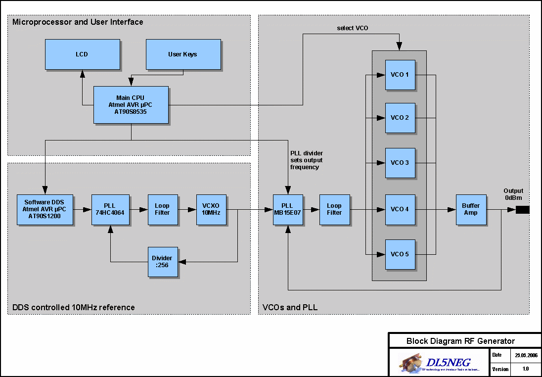
The RF-signal is originally produced in one of 5 VCOs that have overlapping frequency ranges. The software decides which VCO to use, depending on the frequency that is set by the user. The selected VCO is phase-locked via a programmable PLL, in order to generate the wanted frequency.
See the block diagram below for an illustration of the architecture (click on the picture to enlarge it).
2. The frequency ranges of the VCOs
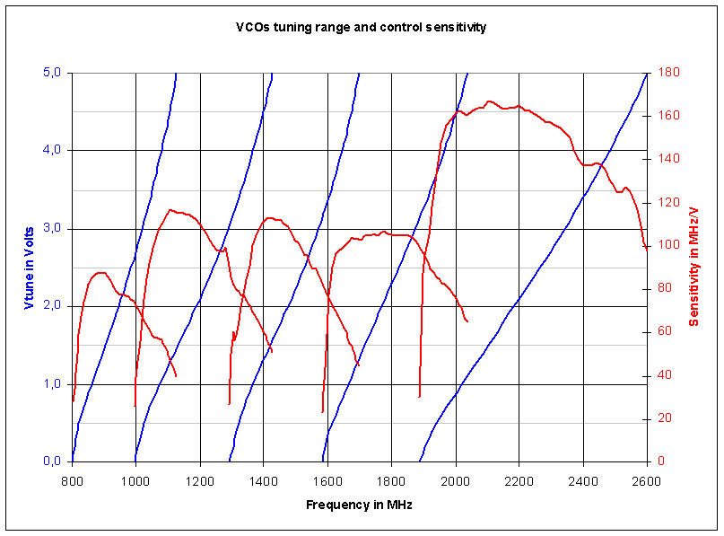
The VCOs were developed especially for this generator. As can been seen in the chart below, the frequency ranges are overlapping, so that every frequency from 800MHz to 2.5GHz can be generated.
3. The way to very fine frequency steps – the tunable reference
The 10MHz reference frequency for the PLL is produced by a software-DDS system running on an extra microprocessor. This enables a 100Hz step width for the full range of 800MHz to 2500MHz.
a) The principle:
The software DDS running on a AT90S1200 is producing a 39kHz signal that can be adjusted in very fine steps. A 10MHz VCXO (voltage controlled crystal oscillator) signal is divided by 256 (10MHz : 256 = 39kHz) and phase locked to the DDS signal. The loop bandwidth of the PLL loop is very small (around 100Hz) so there are no DDS spurious components on the 10MHz signal. The pulling range of the VCXO is around 100ppm, giving a pulling range of 100kHz if the reference is used for a 1GHz PLL.
b) The implementation:
The hardware for the DDS is a AT90S1200 running on +5Volts supply voltage and being clocked by a temperature compensated 13MHz crystal oscillator. (Yes I know, the AT90S1200 is only specified up to 12MHz, believe me the 8% higher clock rate is no problem at all.) The VCXO is a standard Clapp transistor oscillator with a normal 10MHz crystal. To make the crystal oscillator a VCXO I have put 2 varactor diodes (SMV1253) between the crystal and ground. A chip inductor in series to the crystal brought the frequency back to 10.000MHz so I can now tune from 10.000 to 10.001 MHz.
c) The software
The software is written in assembly language of course, since every clock cycle is important for this application. The desired frequency is set via a 3wire-bus from the main CPU in my generator. Normally the DDS is running at full speed without even checking the input bus. If the main CPU wants to set a new frequency it triggers an external interrupt which stops the DDS work. In the interrupt service routine the DDS-software reads 3 bytes via the 3wire-bus, then it resumes the DDS work. I suggest you simply have a look on the source code. If you have questions just don’t hesitate to contact me by email and I will be glad to advise you.
Here is software for download, both the assembly source code and the binary code, contained in .zip container.
The assembler source code: dds.asm
The readily assembled hex code: dds.hex


