Abstract
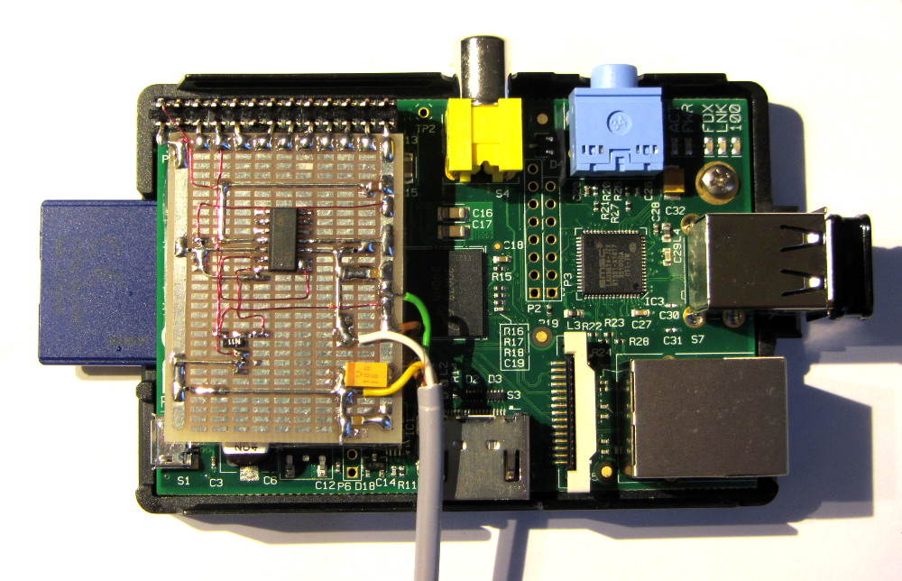
This article describes how to adapt the Ketler/Polar wireless heart rate receiver to a RaspberryPi board.
Motivation
The well established RaspberryPi miniature computer is an ideal platform for longterm heart rate monitoring at home. It uses very little power and has close to unlimited storage capacity (relative to this application) on its SD Card. It also features easy network access via LAN / WLAN (using a very cheap USB-WLAN adapter). So there is no need to connect a monitor, the results can be downloaded to any other device within the network. If desired, it can connect to small or even larger monitors for displaying statistics or real time data.
Challenge
There are a number of descriptions out on the web, for building a home-brew heart rate sensor. Most of them are based on optical measurements on the ear or on a finger. They work reasonably well (I have made one myself some years ago), but they are not very convenient for long term measurements.
Another way of reading the signal from a human body is via electrical signals, picked up on the patients chest. This is how professional medical equipment works. And there are chest belts available from Polar (and others) that sends a wireless signal (on 5.3kHz) to a display, which is typically within a watch on the users wrist, for every heartbeat that is detected.
If one could reliably receive those signals with some kind of home made electronics, it would be easy to store the information with a RaspberryPi, or any other kind of processor equipped device.
Solution
While it is possible to build such receivers with discrete components, it is quite a challenge and it is unclear if the same results are possible to achieve, that commercial equipment offers at very low prices. There is a small adapter available for Ketler home training equipment, that fits into the ear clip connector, giving the training equipment the capability to read wireless signals from Polar chest belts. These adapters are available for little more than 20 Euros from several online shops.
The problem is, that there is no interface description available for these little devices, so I had to do a little trial-and-error investigation on them. Using my digital oscilloscope, and some hints on the pinning of the original ear clips, I was able to develop this simple electronics, that pimps up the signals to a compatible level with the RaspberryPi GPIO inputs.
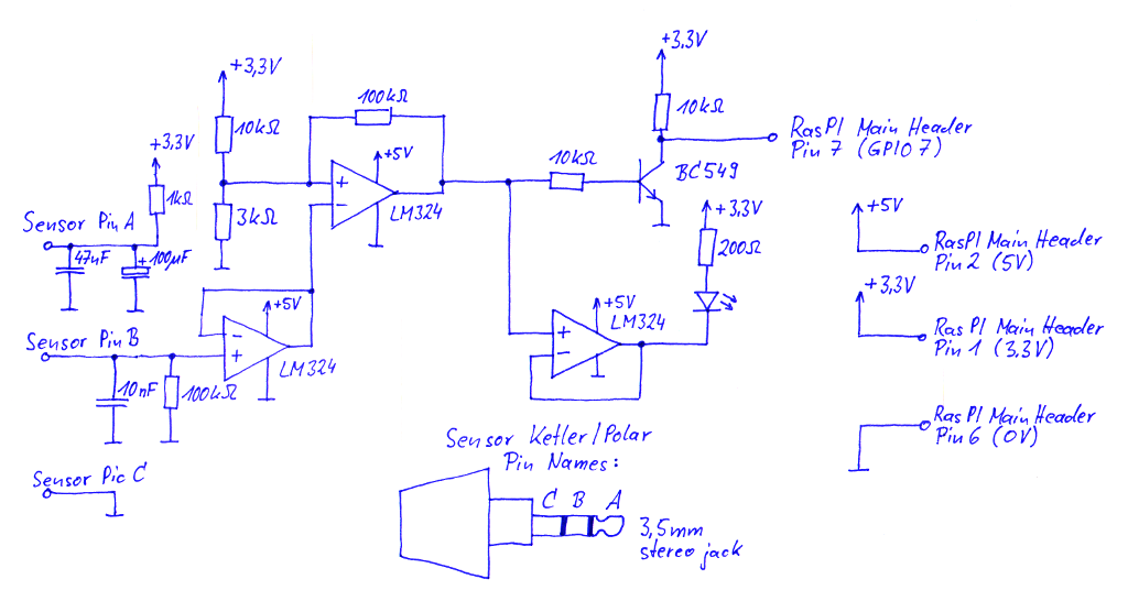
Schematic
Measurement Results on the Sensor
Sensor Supply Voltage
The sensor starts to output pulses at the middle ring of the 3.5mm connector, when 1.15V or more are connected to the tip of the connector, with the upper ring used as ground connection. I have no idea what the specified supply voltage range is, so I decided to run it on the RaspberryPi’s 3.3V supply, with a 1kOhm resistor in series. In that configuration, the sensor draws about 0.4mA of current, so with the voltage drop on the resistor, it runs on 2.9V.
Sensor Output Signal
The output signal apparently has a very high impedance. It can only drive very little loads, without degrading too much. On the other hand, it appears to need a certain pull down resistor, otherwise the signal floats somewhere in the middle of the supply voltage.
With a resistive load of 100kOhm, the output pulses are about 1.6V during the pulse and basically 0V in between. The length of one pulse appears to be constant at 32ms. There is one pulse per heart beat, provided the chest belt is within the operation range, which is about 80cm.
The sensor output is very sensitive to connected wires, and tends to starts showing some kind of high frequency oscillation, when a wire of more than a few centimeters is connected. A little capacitor (10nF) towards ground fixes this tendency, without noticeably hurting the signal.
Circuit Description
The first stage of the circuit is a simple unity-gain amplifier, to isolate the sensor from the following stages.
The second stage is a limiting comparator, with a little hysteresis to avoid glitches. The threshold level is about 0.75V (roughly half of the input signal level), the hysteresis is about 80mV.
Since 3.3 Volts is too little for the supply voltage of the used LM324 operational amplifier, I have used the unregulated 5V supply from the RaspberryPi Board, which comes directly from the used external power supply. That gives the LM324 an output voltage range of roughly 0 Volts to 3.8 Volts. To make sure that the used GPIO input of the RaspberryPi gets exactly 3.3 Volts as high level, independent of the voltage of the external power supply, I have used a open collector transistor circuit with a pull up resistor connected to 3.3 Volts.
The LM324 integrated circuit holds 4 operational amplifiers in one housing. So I had some spare left and used one as a LED driver amplifier. The LED flashes with every pulse that is received from the sensor.