Motivation
Some of the ultra-low-cost devices within the ATMEL AVR microprocessor family have a programming interface that is different to the well known AVR ISP (in-circuit-programmer) interface. The traditional interface works with three lines: MOSI, MISO, SCK. In addition to that, the Reset line must be controlled towards the target. The new interface, called TPI, knows one line less, thanks to the data line being bi-directional.
Now the problem for the hobbyist is, that many of the rather low cost programmers on the market, don’t work on the TPI interface. The only commercially available programmer that I know of (at least for Linux environments) that features the TPI interface, is the ATMEL AVRISPmkII. I have already published an article that describes how that programmer can be used with a Linux operating system.
Being an ambitious hobbyist, I like to have control over the tools that I use, so I decided to build myself my own programmer for the TPI interface. There is an application note from ATMEL (AVR918) that describes such a programmer. This article is largely based on the application note, but it actually fixes some imperfections of the original ATMEL publication.
Hardware
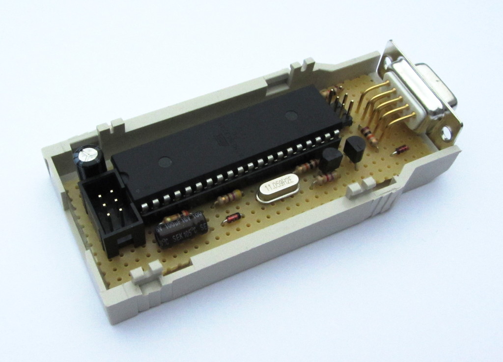
The hardware setup is described in somewhat generic terms in the ATMEL application note AVR918. I have added the missing details to the schematic and made everything working successfully. The heart of the circuit is a ATmega324p microprocessor. In this application it features three interfaces to the outside world:
- The traditional AVRISP interface, to actually flash the firmware into the programmer itself.
- A serial RS232 interface to the host, which can be a RaspberryPi, or an PC with Linux or some other operating system on it. Of course the rather outdated RS232 interface can be converted to USB, using a cheap and easy-to-get interface converter.
- The TPI interface to the target chip, which can be any ATtiny4, ATiny5, ATtiny9 or ATtiny10.
My schematic is available for download in PDF format.
Firmware
The firmware is in principle available from ATMEL, as part of the AVR918 application note. It can be downloaded in source and readily compiled (folder AVR918_HEX_FILES, file ‘avr918_ATtiny4_5_9_10.hex’) for the ATmega324p.
However, while working intensively on the front-end software for the programmer, I stumbled upon two rather significant imperfections (to avoid the term ‘bug’).
- The automatic address incrementation during the flash process does not work correctly. I was able to work around this in my front-end software, by sending the address explicitly for each 16bit word that I flash into the target. Needless to say that this makes the flashing more time consuming (however that does not matter too much, as the memory of the tiny devices is so small, that we anyway talking about less than 2-3 seconds).
- Even more inconvenient, and not possible to work around, is the fact that the TPI interface on the target is not correctly closed after the flashing procedure. Due to that, a power cycle of the target device is needed, to actually start the newly flashed firmware. I have patched this flaw in the firmware and – et voilà – the target device starts to work nicely right after the firmware was flashed.
I have contacted ATMEL about this, but so far I have not received an answer back. Since I am not sure about the license terms of their firmware, I cannot re-distribute the patched firmware here.
What I can do however, is to publish the more or less completely re-written function, that fixes the main flaw, that prevents the immediate start of the new firmware in the target.
[Rewritten function to be published here very soon.]
In addition, I have created a makefile for Linux based systems, that allows to easily compile the complete firmware from the AVR918 application note, with the patch described above.
[Makefile to be published here very soon.]
Alternatively I would be willing to share my firmware with you upon your email request. (See main page for my contact information).
Oscillator calibration for exact system clock
The ATtiny devices run on an internal oscillator that is adjusted to +-10% precision at the ATMEL factory during production. For some application, e.g. serial RS232 communication, a much better precision is needed. This can be achieved by adjusting every single device. There is a 8bit register in the device (called OSCCAL) that allows to adjust the oscillator in quite a wide range. The way to have the device working at the precise frequency is like this
- load a special firmware into the ATtiny (available for download below)
- apply a known, precise frequency (32kHz in this case) to the device, this is done by the programmer described above, when then “Y” instruction is sent to it from the PC
- have a firmware in the ATtiny to compare the applied frequency with the internal system clock by using the internal hardware timer
- try out different OSCCAL values, to find the one that gives the closest match
- write the found value into a certain cell of the flash memory (there is no EEPROM)
- at start of the regular firmware later on, read the value from the flash and write it to the OSCCAL register to adjust the frequency
There is an application note from ATMEL (AVR057) that describes this procedure, but I was not too impressed with the firmware that they proposed to run in the ATtiny for the frequency comparison routine. So I decided to write my own. It is completely written in C and demonstrates that quite extensive and complex routines can fit into the 512 byte of flash memory.
You can download my firmware in source and as compiled binary here.
Front-end Software for Linux (e.g. RaspberryPi with Raspian)
I am currently working on a front-end software (similar to the well known avrdude), that can be used to read, write and change fuses in the target device. It works on Linux based systems and is especially tested to work on the RaspberryPi. (That makes it possible for me to work on my hobbyist projects from the comfort of my living room, while the target, the programmer and RaspberryPi are located in my working room, with the RaspberryPi being remotely controlled from my laptop computer.)
[Front-end software to be published here very soon, it is working well in the beta version already]