1. What is it good for?
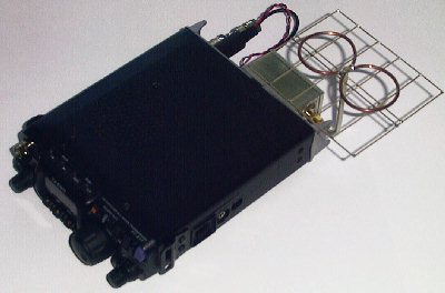
It is a very small receiver converter that can be plugged to the backside of the battery powered portable transceiver FT817 from Yaesu. It runs on the batteries of the transceiver (no changes to the transceiver necessary). So the FT817 together with the converter forms a very small, high performance receiver for 2.3GHz amateur radio signals. The system is ideal for portable and/or outdoor usage. Normal setting is that 2320MHz is converted down to 432MHz, but with only a minimal change in the software of the microprocessor in the converter, it can also be used for satellite (OSCAR) signals.
2. How does it look like?
The saying goes that a picture tells more a thousand words, so please have a look on my picture gallery.
Closeup of the converter on the backside of the FT817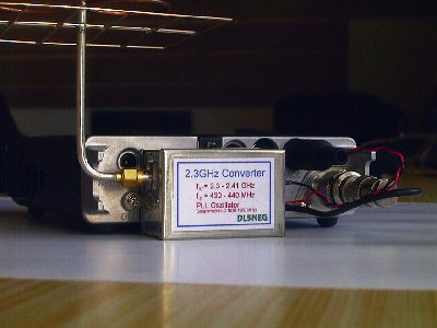 Another closeup from a different angle
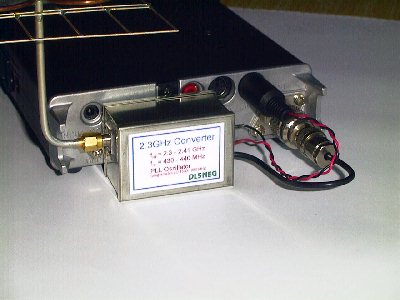 Just the converter, showing the BNC and mini-DIN connectors to the FT817
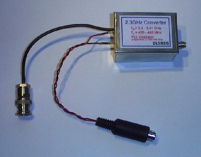
3. How does it work?
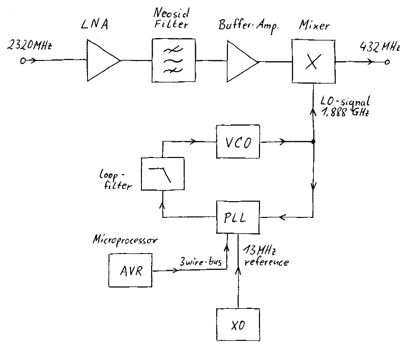
Well, the principle of converters is always the same: The incoming signal is amplified first in a LNA (low noise amplifier). Then it is filtered to avoid unwanted mixing products later on (the so called image-frequency is suppressed). After another amplifier, the signal is fed into a mixer where it is mixed with a local oscillator signal. One of the mixing products is the input frequency minus the local oscillator frequency. That product is fed to the FT817 where it can be received just like any other signal that has never been on 2.3GHz.
Most converters us a crystal oscillator signal that is multiplied a couple of times to generate the local oscillator (LO) signal. The advantage of this principle is an extremely clean LO signal. The disadvantage is the large board space that is required for the filtering after each multiplication stage and the fact that the LO signal is fixed on one frequency. In my approach I have used a 13MHz crystal oscillator signal as a reference, a 1880MHz VCO and an integrated PLL IC to generate the LO signal. A small microprocessor tells the PLL which frequency it has to generate (this happens only once at power-on, then the micro falls asleep and does not consume any significant current). So it is just a matter of changing the software and retuning the adjustable input filters to change the frequency, that can be down converted to 432MHz for the FT817.
Here is a block schematic for a better understanding of the explanations above.
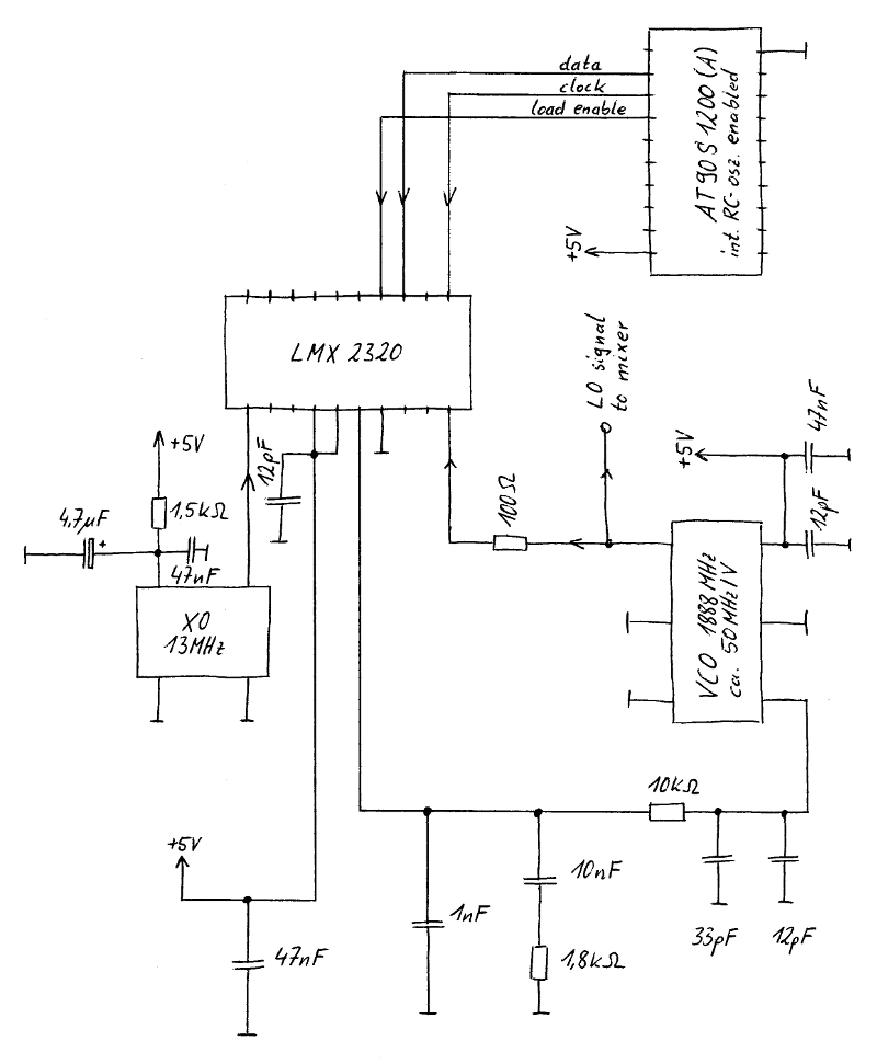
Ok, now lets talk about the building blocks that are mentioned in the block diagram. First of the all: the LO signal generation. A 1880 MHz VCO (Voltage Controlled Oscillator, sensitivity around 45MHz/V) is controlled by a National Semiconductor PLL IC LMX2320. The PLL is programmed by an Atmel AT90S1200 AVR microprocessor. The AT90S1200 has the RCEN (RC-oscillator ENable) bit set, so it does not need any external components, no crystal, no resonator, real zero component count. The AT90S1200 can be ordered with that bit set (it is called AT90S1200A then), or you can set that bit yourself. It is stored in a non-volatile memory, so it will stay set, even without supply voltage.
Have a look on the schematic to see how the PLL, the VCO, and the processor are connected.
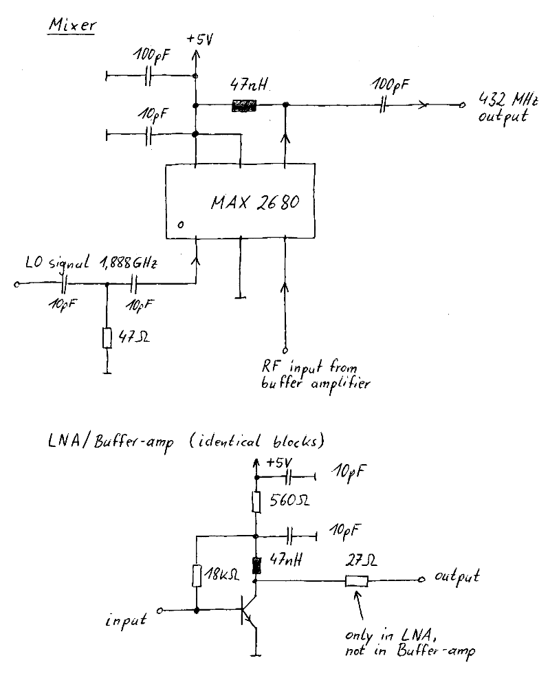
The LNA and the buffer amplifier are build using BFP420 bipolar RF transistors. At the chosen bias point, they have their best impedance for minimal noise right at 50 Ohms (at frequencies around 2.4GHz), so no input matching is necessary. For filtering the signal, I have used readily available helix filters from Neosid. The mixer is an integrated down conversion IC from Maxim, the MAX2680.
Here is the schematic of the amplifiers and the mixer.
4. How is made? Is there an etched board?
The converter is handmade as a prototype, just one part for myself. And no, there is no etched board. And you do not need an etched board for 2.3GHz designs if you do not use stripline technology. Just make everything as tiny as possible and 2.3GHz circuits are no black magic. Making everything so small may not look so nice, but it works very well. For all of you that have a hard time to imagine how it may look like, I have a few more photos here:
Top side of the board (VCO, PLL, amplifiers, mixer)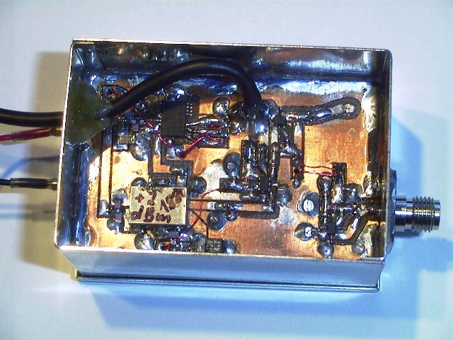 Bottom side of the board (reference oscillator, microprocessor, helix filter)
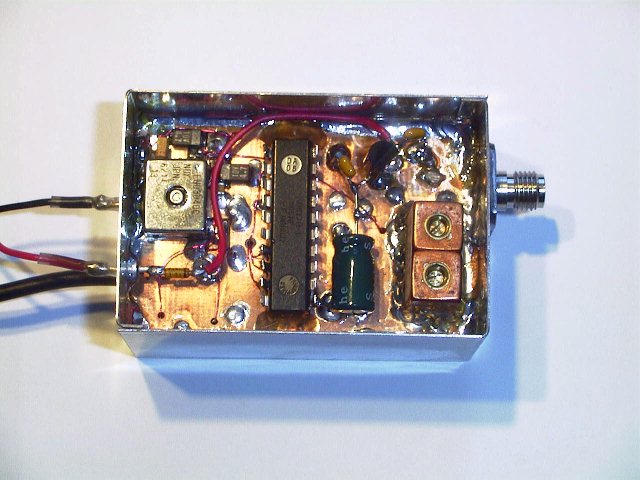 The microprocessor is in a DIP20 package. A SMD package would have been also available, but that costs a few cents more and the DIP part did also fit. So I used the PDIP chip and mounted it dead-bug stile, i.e. glued down with the legs in the air. So it looks like that.
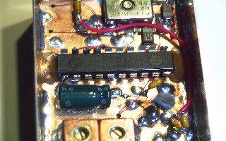 The reference oscillator and the helix filter are mounted just as defined by the manufacturers.
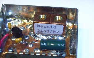 The mixer and the components around it are done as compact SMD design.
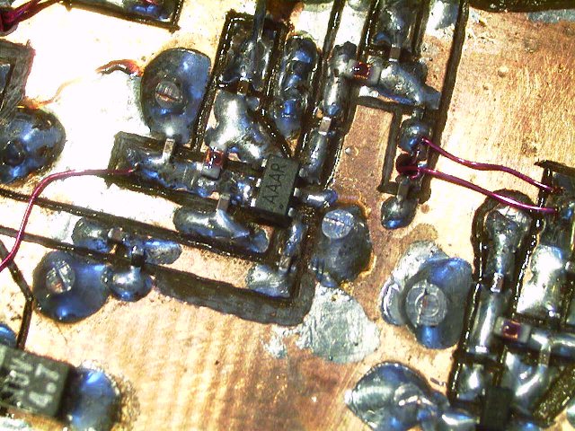 From the LMX2320 PLL IC I have broken off the pins that I did not need. This way it was not very tricky to solder to the remaining pins of that fine-pitch IC.
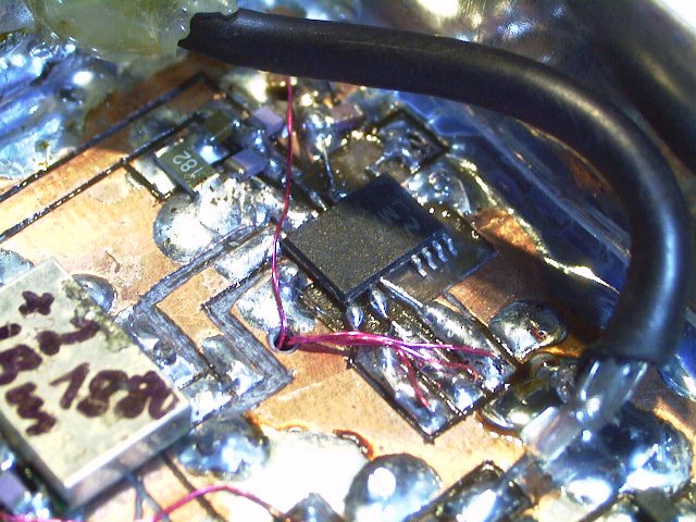 The amplifiers may be a bit hard to recognize, therefore I have marked them in the picture. The helix filter is mounted from the backside between both amplifiers.
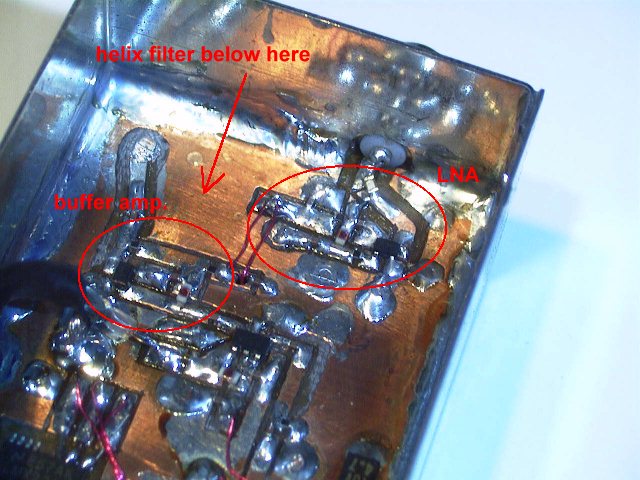
5. So, what about the software for the microprocessor?
The software if of course also available, even with the source code for those who want to experiment with it. (All three files are contained in one .zip container).
- Software in Intel-Hex format for direct download to the microprocessor
- Data file that holds the PLL programming bits for the internal EEPROM of the micro (must also be loaded!)
- Assembly source code for those that are interested
6. How good is it? Can I use it or is it just a toy?
The performance of the converter is really good. A few years ago it would have been called outstanding. Today there are a few designs available with a somewhat better noisefigure (mine is around 1.5dB) and cleaner local oscillators. But I am not aware of any other design that comes even close to my small size.
One word about LO phase noise. In the beginning of this page I have stated that multiplied crystal signals are extremely clean. And I do admit that a PLL signal will never be that clean, regardless how hard you try. But the phase noise of my LO signal is more than sufficient for both FM and SSB operation. Experience shows that everything below -70dBc/Hz @ 1kHz is good, below 80 is more than enough. For the converter LO I have measured -84dBc/Hz. Have a look on the plot here.