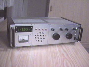
After I had developed a couple of short-wave and VHF-FM Receivers in my spare time, I decided to develop an all-mode Receiver for the 144 MHz amateur radio band, as my university graduation thesis. This receiver has to be able to receive frequency modulated (FM) signals as well as single sideband (SSB) amplitude modulated signals at 144 MHz. The project was supervised and evaluated by Prof. Dr. Ott at the Georg Simon Ohm technical university in Nuremberg, Germany. All copyrights are to the university, which means that you must not use any of these circuits for commercial developments.
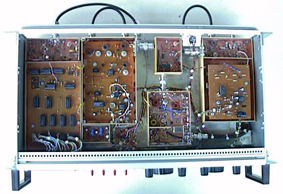
Upper part (demodulators, AGC, frequency counter)
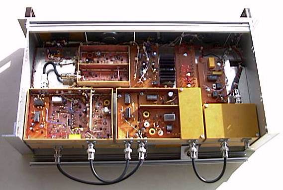
Lower part (LOs, PLLs, preamplifier, first mixer)
The Concept of the 144 MHz Receiver
The receiver is a double-superhet for SSB and a tribble-superhet for FM. The front-end is the same for FM and SSB. After per-amplification the received signal is mixed down to the first intermediate frequency (IF) of 48MHz. A variable gain amplifier can adjust the signal level, based on the control signal from the automatic gain control (AGC) circuit. The signal is then further mixed down to the second IF of 8MHz. The it is further amplified/controlled by another variable gain amplifier. Then the signal is split up for FM and SBB reception. I used a mechanical relay for improved IP3 performance, but a diode switch or a resistive -3dB power splitter should work as well.
In the SSB path, the signal is tightly filtered by a homemade crystal filter, that is just wide enough for typical speach spectrum (around 2kHz). Then the signal is mixed directly to audio frequencies and amplified for the loudspeaker.
In the FM path, the signal is mixed down further to 455kHz, where it is demodulated and filtered by an integrated circuit. The output signal of the IC is then amplified and put on the loudspeaker.
See the block diagram below for illustration.
Despite the fact that the VCO is drawn as a small black box in the picture above, it needs some attention. While a stable free-running oscillator can be build for frequencies up to 10 MHz, it is practically impossible to build an oscillator for 96 MHz that is stable enough for SSB operation. Therefore I have developed a double return-mixing PLL for 96 MHz. Lets have a look at the schematic diagram for the VCO then we will discuss it.
Confused? Don’t worry, it is not half as complicated as it looks. We start at the right. The output signal of the 96 MHz is mixed down to 36 MHz by a crystal oscillator. The 36 MHz – signal is fed into a phase comparator. The second input of the phase comparator is feet by the signal from the 36 MHz VFO.
For FM the 36 MHz VFO is free running, controlled by a helix potentiometer. The long term stability of the 36 MHz VFO is sufficient for FM and the frequency range of 2 MHz is enough to cover the European 144 MHz Band. It should be no problem to get a bigger range for covering of the US 144 MHz Band.
For SSB operation the 36 MHz signal is mixed down to 6 MHz. This 6 MHz signal is again feet into a phase comparator where it is compared to the signal of the 6 MHz VFO. This way the stable 6 MHz VFO is able to control the 36 MHz VFO which again is able to control the 96 MHz VFO. A well designed 6 MHz VFO is by far good enough for SSB, so the 96 MHz VFO in this system is good enough too. (For experts: since the time constant of the PLL loop filter is quite large, the phase noise of the 96 MHz VFO is significantly reduced also.) The frequency range of the 6 MHz oscillator is only 500 kHz, but this is completely sufficient since all SSB/CW operation is located in the 144 – 144.5 MHz area.
The Local Oscillator System
Lets start with the 6 MHz oscillator. The highest priority in this circuit is its long term frequency stability. You might be surprised about the many buffer stages. I tried to make sure that the output frequency is 100% independent of the circuit load (and it seems that I even overdid it a little bit).
Now we will have a look at the 36 MHz oscillator. It turned out that the shunt diode increase the phase noise. Therefore I recommend to skip it. The 22pF coupling capacitor can be increased to 27pF which gives a bit more tuning range. All capacitors in the resonator (i.e. between the BB204 and the J310) should be “zero temperature drift” types. The trimming capacitor is a silver-air-trimmer, but the long term stability will not decrease a lot if you use a cheap trimmer since the influence of this capacitor is quite small.
The 36 MHz oscillator above is phase locked to the 6 MHz Oscillator by the following circuit.
And finally here is the 96 MHz oscillator which we will feed into the mixer to convert the input signal to the first IF of 48 MHz.
This is the PLL circuit that is used to phase lock the 96 MHz oscillator to the 36 MHz oscillator.