Remote control transmitters, receivers and accessories from Graupner/SJ are widely known in the model flyer’s community. Especially in Graupners home country Germany, they are widely spread and well used by hobbyists and also by competition model pilots. As all the other modern 2.4GHz RC systems from Graupners competitors, the family of “HoTT” products (brand name of Graupner/SJ, used by me only as a reference) features a telemetry functionality, where the receiver in the model can transmit back information to the transmitter that is used by the pilot on the ground.
Graupner offers a very nice variety of sensors, that can be connected to the receiver for battery voltage, barometric height measurement, temperature and even GPS coordinates, etc. In my take, the sensors are reasonably priced, so if time is more valuable to you than money, I propose you stop reading here and order one of the original sensors.
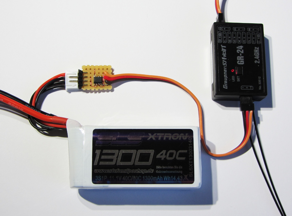
For those that appreciate to do their own electronics and are willing to spend the needed time to build it, here is my report on a home-brew battery sensor, to monitor the battery voltage of a 3S1P LiPo battery (11.1V typical) in a model plane or quadcopter, or car, if you like. I have tested this sensor with a MZ-18 remote control and two different receivers (GR-24 and GR-12L), all of these devices were on the latest firmware from Gaupner as of December 2015. I strongly assume that it also works with other Graupner receivers and remote control transmitters, but I can’t say for sure.
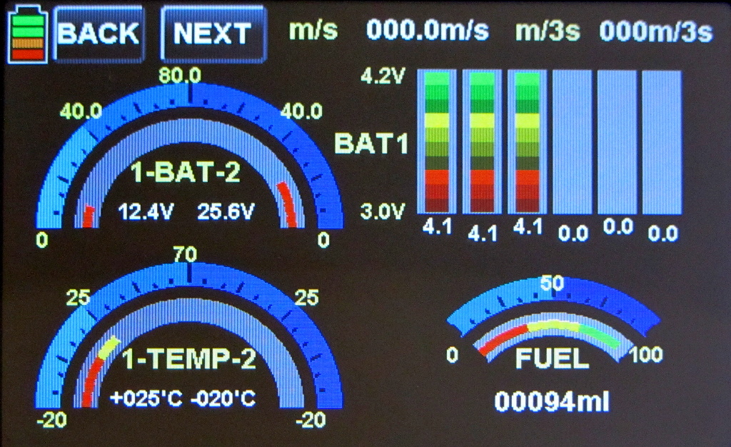
The picture above shows the telemetry screen on the MZ-18, that is populated automatically with the sensor signals. The temperature values are hard coded fake values, to try out if these parameters would also be accepted by the remote control (and yes, they are). The fuel bar is used to show the battery capacity in percent between 3.2V and 4.2V per cell. The fuel level in ml is used to show the said percentage as a number.
Hardware
The hardware is really reduced to a minimum to save material cost, soldering efforts, weight and size as much as possible from a hobbyists view. The circuit consists of little more than a Atmel ATtiny13A microprocessor (around 0,86€ for single pieces), a 3.3V voltage regulator TS5204 CX33 (0.26€), the connector to the LiPo balancer plug and a few chip resistors and capacitors. So in total the material cost should be in the range of 2€ (more or less the same number in US$), plus the cost of cable/connector to the receiver.
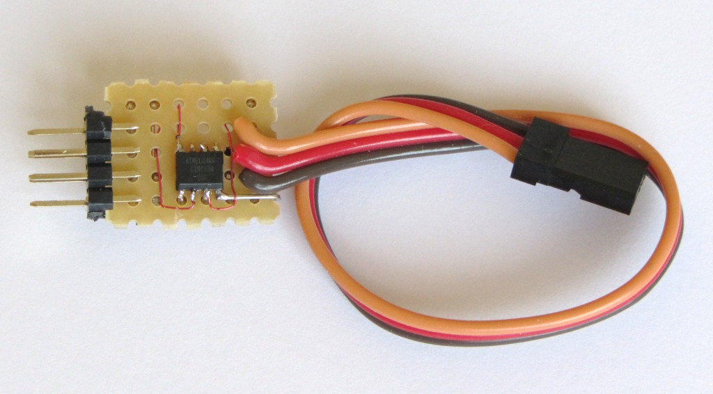
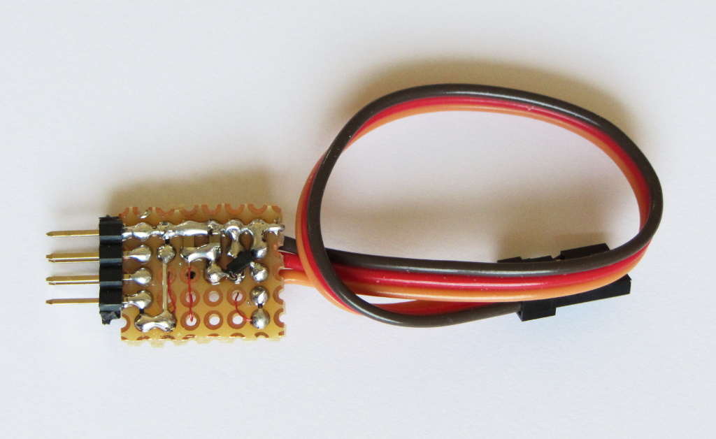
The microprocessor is placed on the top side of a very small prototype board (hole to hole distance is the typical 2.54mm or 1/10th of an inch). On the backside I have mounted the voltage regulator in the tiny SOT23 package, the blocking capacitors and the resistive power dividers. The battery connector can be a simple double row connector, as shown in the picture of one of my first prototypes. In later versions I have used a XH plug, that fits exactly to the balancer connector on typical LiPo batteries. A word of warning here: Since the battery ground is connected via the receiver connection already, you risk a short circuit of your LiPo battery when you connect your battery in the wrong way or wrong polarity. Short circuiting a LiPo battery can be very dangerous! Rather use a connector that cannot be connected wrongly and check your circuit well before you connect the battery for the first time. Operate at your own risk, you have been warned!
For LiPo batteries with multiples cells (like the 3S1P that is targeted with this circuit), it is a good idea to monitor each cell separately. Especially when the battery gets older, it is well possible that one cell starts do die while the others are still good. The total voltage may still be at an acceptable level, while once cell is very close to quit working. This might lead to very little warning time before the model runs out of power.
With that in mind, I have done two versions of this sensor. Version V1.0 is made to keep things as simple as possible. Only the total battery voltage is monitored. The voltage of the 3 cells is simply calculated by dividing the total number by 3. For sensitive applications, I recommend version V2.0, that spends two more resistive voltage dividers and connects them to two free pins on the microprocessor.
The remaining free memory was just about enough for extending the software respectively. Make sure to download the correct combination of hardware schematic and firmware file. The firmware is not compatible between the two versions! I had to change some pins on the microprocessor to free up pins those can act as ADCs.
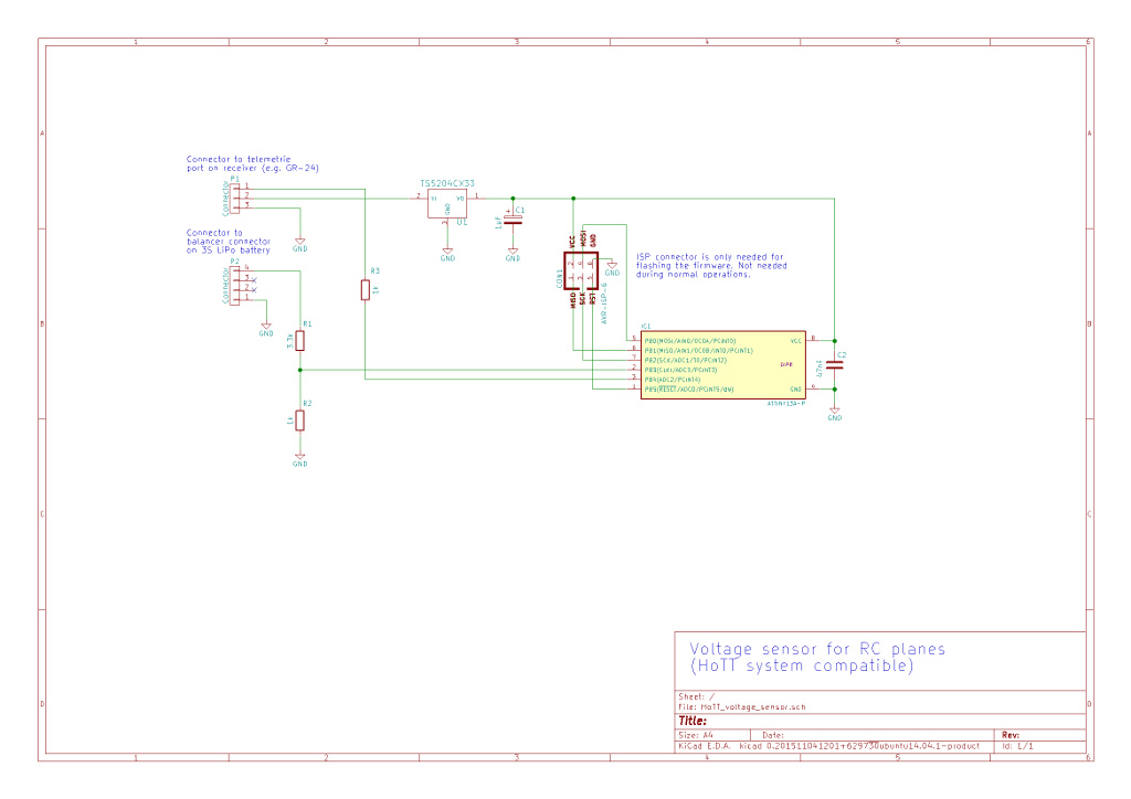
This is the schematic of Version V1.0, which is the simple schematic. Click on the picture to download a high quality schematic in PDF format.
And this is the schematic of Version V2.0, which is able to monitor all cells separately. Click on the picture to download a high quality schematic in PDF format.
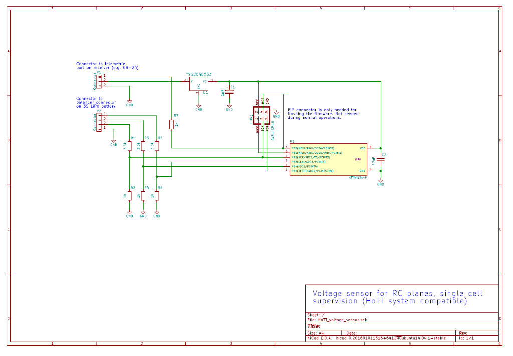
The six pin in-circuit-programming connector is only needed to flash the firmware into the micro processor. I have omitted it on tiny form factor board and have soldered it via some lose wires, that I disconnected when I was done with flashing the software. My goal was to get the circuit extremely tiny, so it would easily fit into my model plane.
You may notice that the resistive dividers are made of quite small resistor values. They do drain the battery with several mA of current. Since the brushless motor of the model will need a much higher current, it does not really matter so much. But I have anyway tried to use resistor values that are ten times higher. I found that the accuracy of the ADCs is slightly reduced, due to the much higher impedance of the signal source. The reading went down by a slight 2-3%. I was able to compensate that in software in a private version, but my stomach feeling is better without such software fixes, so I will probably stick to the shown values for my own applications.
Software
The software was written in C using the well known GCC compiler for Atmel AVR. I have compiled the code on a Linux Mint 17.2 machine, but the same should work on Windows machines as well. Some of the code is slightly done in a way that saves memory, as the ATtiny13A only has 1024 bytes of flash. But most of the code is straight forward and following the typical C structure. Saving memory is mostly done by not using floating point arithmetics and by avoiding divisions that are not by a number that is a power of two. (The compiler is clever enough to replace a /16 for example, by a shift to the right by 4 bits).
As the ATtiny13A does not have a hardware UART, I have written the routines for sending and receiving bytes myself. These routines are well tested in other applications and work very reliably, provided that the clock of the processor is within the acceptable precision (which is said to be 2%, but a bit less accurate typically still works).
The makefile is provided here for reference as well and should work directly, if your AVR GCC tool chain works in general. For more details on the Atmel tool chain, you may want to have a look at his article, which is is for slightly different devices but the tool chain information also applies to the ATtiny13A.
Since the protocol used by Graupner is a serial protocol, very similar to the good old RS232 but with only one shared data line, timing is critical. Ideally a microprocessor with a crystal or at least a ceramic resonator would be used, but that would add significant size, cost and space to the circuit. So I have decided to use a device with internal RC oscillator (the ATtiny13A) and adjust the setting in the firmware for every sample of the used device. The manufacturer Atmel does adjust them to a precision of 10% according to the data sheet, but that is not quite good enough for a 100% reliable serial communication. With the help of an oscilloscope it is very simple to figure out the perfect adjustment of the trimming parameter (called OSCCAL). If you don’t have one, you can still try different values, see which works for you, find the upper and lower limit when it stops working and go for the middle. That should work well. The temperature dependency is rather limited within the typical temperature range and the voltage is very stable anyway, due to the voltage regulator. So if it works on your lab bench, it will very likely work very well in your model.
For me the perfect value (measured on that particular ATtiny13A with an oscilloscope) was 56, so within the first lines of code you can find my entry of this value like this:
#define OSCCAL_DEVICE_SPECIFIC 56
Since high power motors on the model can put quite some ripple on the voltage supply, the analog input level is sampled 8 times with a 1ms delay in between for good statistical separation. The average value from these 8 values is calculated and the result is used as the “true” value, that is finally processed and sent back to the transmitter. Also here the value 8 has been chosen for good memory efficiency, since a division by a number, that is a power of 2 is very simple for a processor, it is only a shift operation. If even more filtering would be required, the next logical number of samples would be 16.
- Software in source and binary, version V1.0 for simple total voltage monitoring
- Software in source and binary, enhanced version V2.0 the single cell monitoring
Connecting the sensor within your model
Generally the connection of the sensor to the battery and the sensor is straight forward. The connection from the sensor to the receiver goes into the telemetry connector of the receiver. On some receivers that port is configurable as normal output or telemetry input, in that case it must be configured for telemetry via the transmitter menus.
During my testing, I found that the process of getting the sensor to work is quite daunting, but that goes for the original Graupner sensor in the same way as it goes for the home-brew version. The receiver stops to check for external sensors after a while, so if you connect the sensor too late, it will never be detected. The best way to overcome this problem during testing is to switch your remote control transmitter off and on, once the sensor is connected. That will trigger a new search for external sensors. In the telemetry screen of your receiver you will very quickly see a “CHK” button that is not reactive, but changes to “NEXT” after a while. When you press it, you get to the new telemetry screen. By touching somewhere into that screen, you will get to the screen shown above (all of this goes for the touch screen transmitters, like the MZ-18 or MZ-24, I am not quite sure how it works on others).
For real live usage in your model plane, I recommend to follow this procedure.
- Switch on the transmitter
- Connect the battery to the receiver, your plane will power up
- Connect the balancer connector of the battery to the sensor within a few seconds
If you find an error or missing or misleading information on this page, I’d highly appreciate a quick hint via e-mail. You will find my address on the main page.