This article is about a microprocessor based sensor interface that connects a cheap and easy to get GPS receiver module to a Graupner RC (remote control) receiver for model airplanes or other remotely controlled vehicles.
After i had successfully completed the HoTT compatible battery voltage sensor, it was time to take on the challenge of getting a GPS sensor to work on the HoTT interface. And since I figured that one microprocessor can take care for both the GPS connection and for measuring the battery voltage, I have combined both functions. So in fact this little circuit replaces both the HoTT voltage sensor and the HoTT GPS sensor.
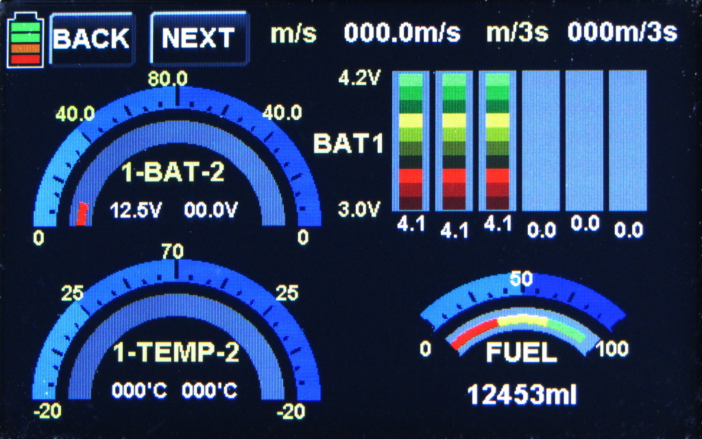
Appearance on the Graupner RC Transmitter
This is how the respective telemetry screens looks on my Graupner/SJ MZ-18 remote control transmitter.
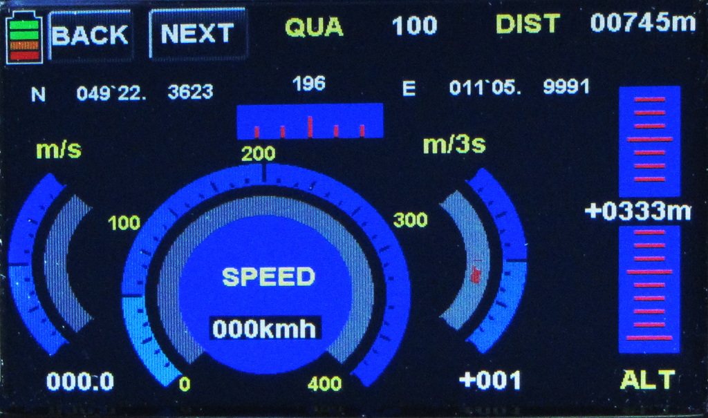
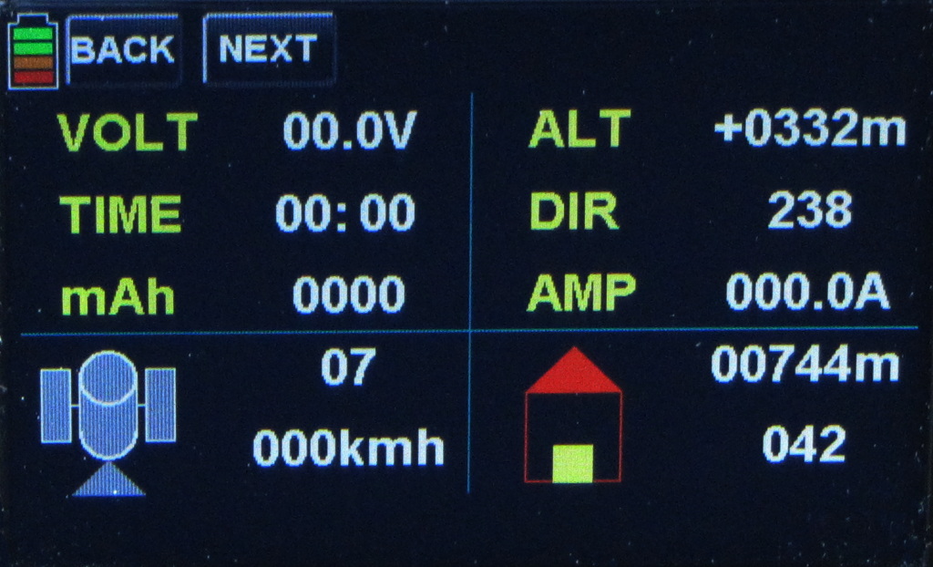
On some of the data fields I took the freedom to use them differently then defined by Gaupner. Especially the distance and the direction relative to the starting position (lower right corner of the 2nd screen, with the little house) I found rather useless, as it is basically impossible to look at your model plane in the air and read the numbers from the transmitter display at the same time. So I used that fields for the precise time (UTC) that comes from the GPS. I figured it would be a waste not to have this information as part of the recorded data file. The example in the picture was taken at 07:44:42 a.m. UTC. The hours and minutes are part of the data record that gets written to the SD card in the Graupner RC transmitter, e.g. on the MZ-18 that I use.
As explained above, the circuit behaves in fact like two different sensors, so it also measures and processes the battery voltage. In order to keep the circuit and the wiring inside the airplane model simple, the battery sensor is based on the more simple one of the two versions that I have published earlier, so only the overall battery voltage is measured. For details see the page on the pure voltage sensor.
Post-processing of recorded GPS data
Since all the data storage on GPS and other telemetry data is done in the transmitter, the collected data can be post-processed just like any other data collected from an original Graupner/SJ sensor. As I prefer to work on Linux machines, I do not use the Gaupner PC software, but evaluate my data with dataexplorer, a free software that works for a number of different data formats. It can also export the data to spreadsheet programs like Excel oder LibreOffice (OpenOffice) Calc. A practical example of such an export is shown below.
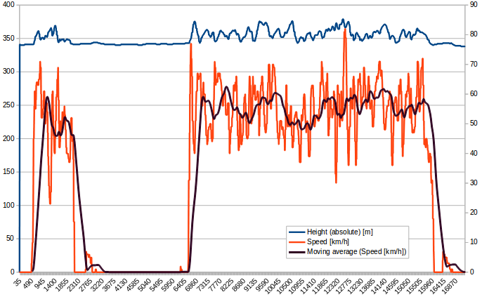
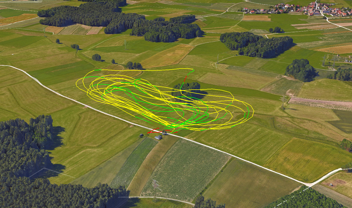
Besides the option to do some technical analysis based on the recorded data, there is of course also the possibility to create a nice showcase, by displaying the recorded flight path in a Google Earth 3D plot like shown below. For the export of the data I have set the color coding to represent a range of flight speeds for each color.
Hardware
The hardware is in fact rather simple, so the circuit should be very easy to reproduce. No special equipment or adjustment process is needed. The heart of the circuit is an Atmel ATmega8(a) microprocessor. It receives the position data from a cheap GPS engine (around 20€ from Amazon). Additionally it measures the voltage of the LiPo battery with its internal ADC via a resistive voltage divider. The resulting information is then forwarded to the Graupner receiver in the remotely controlled model via the HoTT interface.
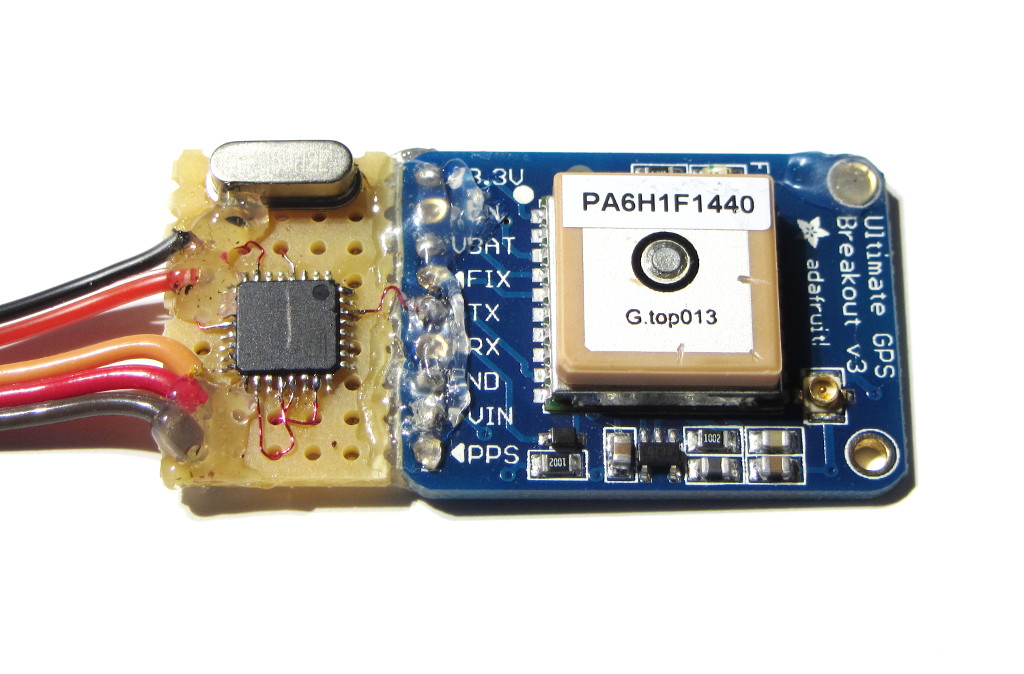
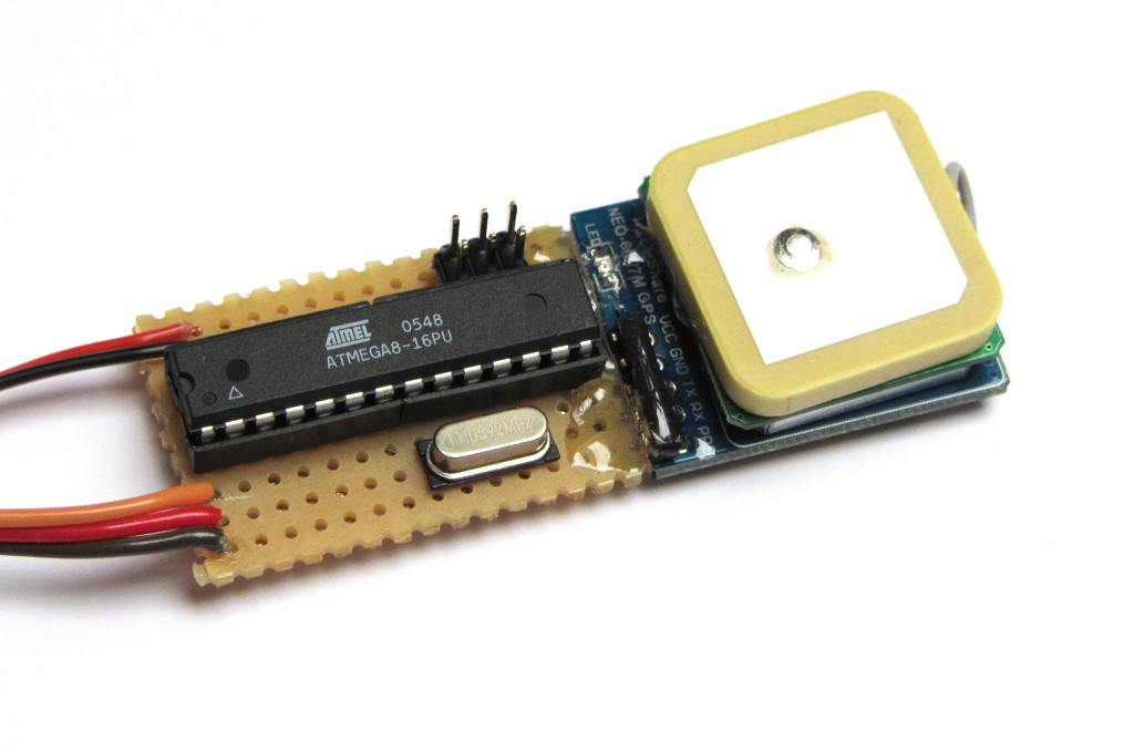
The circuit is tested with two different GPS engines. The first one is the Adafruit GPS v3, which is really small and light weight but a bit more expensive. The second one is the really cheap NEO-7M-C GPS module with active antenna from Amazon.
The Adafruit module I have extended with this circuit in SMD components, to save as much space and weight and possible.
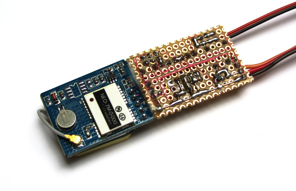
The Neo-7M was a bit bigger and heavier anyway, so I did not bother to make this circuit very small and rather tried it with a ATmega8 in a dual inline package.
On the backside I have in fact used some SMD components, mainly the voltage regulator and the chip resistors.
For compatibility with this project, the GPS engine needs to send out the data on a serial interface with 3V (or 3.3V) positive levels, at a data rate of 9600 baud, 8N1. The needed NMEA messages are $GPRMC and $GPGGA, which are really the most commonly used messages. So chances are really good that your cheap GPS engine will provide these messages, if you have no chance to check that in the data sheet before your purchase.
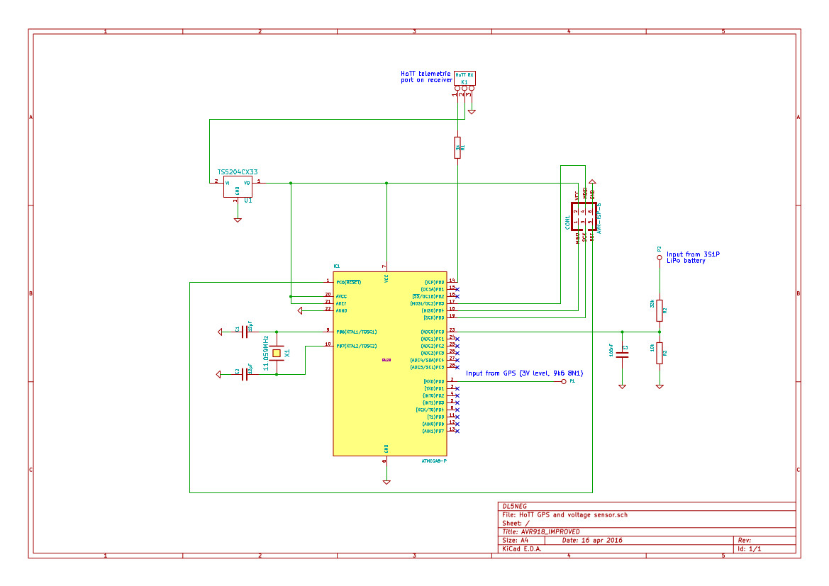
Below you find the schematic for the PDIP (dual inline package) version, which is probably easier to copy. Click on the picture to get a high quality PDF version of the schematic. Contact me if you need help to adapt that to the SMD version.
Software
The software for the ATmega8 was not really trivial. Since it has only one hardware UART, and that is needed for the connection to the GPS module, the HoTT interface needed to be done purely in software. The software interface is blocking on the receiver side, that means it stops the execution of the program flow until an new HoTT request comes ins. In order to be able to listen on both interfaces simultaneously, a very short interrupt routine is handling the processing of received data fro the GPS, without hurting the HoTT timing beyond an acceptable level.
For ease of reproduction, I have added a crystal to the circuit, so no calibration of the internal oscillator is needed. Anyone that wants to eliminate the crystal is encouraged to have a look at the ATtiny13A based RC voltage sensor, I have shown there that it is indeed possible.
The software is published here under the GNU GPL v3. It contains both the source and the binary files and also the make file to build the software with the avr-gcc compiler, that is freely available for Linux and Windows. The binary is tested successfully on both a ATmega8A in a 32pin SMD package, as well as on a ATmega8L in a 28pin dual inline package.
- Download the software here: Source Code, Binary, Makefile, all packed in one zip file
Practical results
I have flown two builds of this sensor on different model airplanes and the results were absolutely pleasing. I was able to record rather precise GPS positions in latitude, longitude and height. Processing the data with data explorer and Google Earth gave exactly the information and results that I were expecting.
The only small limitation that I can see is the fact that cheap GPS engines send the position only once every second. So if you fly wild maneuvers with your small model plane, you may notice that you can’t see every small details of your flight path. For somewhat bigger and less agile models, this effect should not be noticeable.