What is it good for?
The AT90S1200 RISC Microprocessor (AVR family) is a very neat component to program a PLL synthesizer or for doing other rather trivial tasks in a radio circuit. It is reasonably cheap, easy to program and a nice integrated development environment is available for free from the manufacturer ATMEL. And the best thing about it: It has an internal RC clock generator so it does not need a crystal, in fact it does not need any additional components at all. The internal oscillators frequency is somewhat temperature dependent, but for most applications it doesn’t really matter how fast exactly the processor works. The only problem is that it is not possible to activate this internal oscillator with one of the (homemade or cheap-to-buy) serial in-circuit programmers. (The fusebits are only accessible in the parallel programming mode.) ATMEL sells a variant called AT90S1200A that has the internal oscillator activated by default. Unfortunately it seems to be impossible to get this variant here in Germany and from folks in the US I have learned that it is available, but more expensive in the US. The circuit published here is able to activate the so called RCEN (RC oscillator ENable) fuse bit which is non-volatile and will be set forever unless you put it in this circuit with another firmware, to deactivate it.
How does it work?
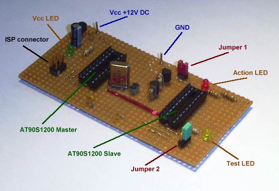
It uses another AT90S1200 (oh boy I love this smallest part of the AVR family) as a master, that sends all the necessary signals to the slave (the one that shall have the RCEN bit set). The hardest part was actually to extract all the necessary signal sequences from the datasheet. (It took me a full weekend to really understand everything and build the circuit.) The master has a crystal attached, so it works in no special mode or such. The master socket can also be used to plug in any AT90S1200 (RCEN set or not) to download software with any serial programmer. (If you don’t have one surf the net, there are lots and lots of ideas. I use a homemade one as described on the ATMEL page in application note 910.)
Schematic Diagram
What are the necessary steps to set the fuse bit in a CPU?
I would not claim that every step that is mentioned here is absolutely necessary. But if you do it like that, you will be in control of the situation at every point in time. For all coming steps I assume that the circuit is supplied with +12Volts DC. A cheap power supply will do, the circuit uses only a few mA of current. I use +13.8V from my amateur radio power supply and it works fine for me. If you have no idea where to get +12V then use your cars battery but be careful, a short-circuit can be dangerous.
1. Plug in the slave in the master socket first and download the following test software (any serial programmer with the ATMEL defined plug can be used). It consists of only a few commands that make a LED on one of the ports flash. We will use this later on as an indicator to check if the CPU is able to run without a crystal. (The flash memory that holds the software in a AT90S1200 is not affected by setting the fuse bit.)
- rcen_test.asm (Assembler source code for those who are interested.)
- rcen_test.hex (Hex-File which can be loaded into the CPU directly.)
2. Take out the slave of the master socket and put it in its own socket at the bottom of the board. Then take another AT90S1200 and put it in the master socket. This one will not be changed in any way and can be used for other applications after the job is done. Download the software for the master. This is the one that contains the know-how, on what kind of signals must be sent.
- set_rcen.asm (Assembler source code for those who are interested.)
- set_rcen.hex (Hex-File which can be loaded into the CPU directly.)
3. Remove Jumper 1, this cuts the connection between the Reset pin of the slave and the control circuit from the master. So the slaves Reset pin is released and will be drawn to high by the internal pull-up resistor. Remove Jumper 2, this cuts the connection between the masters clock signal (driven by the crystal) and the slaves clock input. If the LED is flashing already then you can stop at this point, the RCEN bit in your slave is already set. Usually nothing is happening now, so continue with step 4.
4. Put Jumper 2 in the left position, this establishes the connection between the master clock and the clock input of the slave. The slave is now running on the masters clock signal. Now the LED at the slave must flash, otherwise something is wrong and you should search for the problem before continuing.
5. Now things are getting serious. Disconnect the supply voltage. Put on Jumper 1, now the master can switch the +12V through to the slaves reset pin. (This is necessary to enable access to the fuse-bits.) Put Jumper 2 in the right position to connect the clock input of the slave to the master. The master can now put arbitrary signal sequences to all slave pins, including the clock input.
6. This is the big moment: Connect the supply voltage. The LED that is connected to the master will flash for a very short moment and that’s it, the fuse bit is set. You don’t believe it? Go ahead and remove both jumpers and you will see that the slave is able to make the LED flashing without any connection to a clock source. If you use a crystal around 4 MHz for the master you will recognize that the LED is flashing about 4 times slower now. This is perfectly normal, the internal RC oscillator that is now activated runs at around 1MHz (somewhat depending on the temperature of the device).
Its easy, isn’t it? Well I admit that is was merely something personal between the datasheet and myself. After I had tried to understand it for the first time I could not stop until I had proven that I can make it work, tricky or not. And I had just started to build the 13cm to 70cm converter for the FT817 and really needed a solution for the digital part that would fit in the small space that was left in the box. And now that I have it, I would say it was worth the effort. I have so many circuits with PLLs that all needed external digital boards for the CPU before. Now I simply glue (dead bug stile, if you know what I mean) a AT90S1200 with RCEN bit enable at any free place inside the RF module. I just have to connect +5V and GND, as well as the program lines to the PLL (usually a 3wire bus or a I2C bus). And a friend of mine has build a nice little adapter for the SMD version of the AT90S1200 so I can connect this to the fuse-bit blower as well.
If this was all a bit confusing for you, but you would still like to build yourself such a circuit just don’t hesitate to contact me by email and I will be glad to advise you. You will find my email address on my main page.